


7
Installation
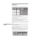
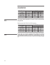
Torque hub assembly bolts 11 according to the following table:
Fan Diameter
inches
Flange Type Bolt Type
Bolt Torque
N·m ft·lb
84" to 96" Type 115
M16 cl. 8.8 230 169
M16 cl. A4-70 126 93
M16 cl. A4-80 168 124
108" to 168" Type 190
M20 cl. 8.8 447 329
M20 cl. A4-70 246 181
M20 cl. A4-80 328 241
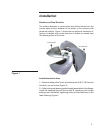
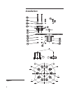
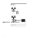
3––Hub into driveshaft installation (Figure 2).
• As for the hub with cylindrical bore, the hub is bored to attach
directly to the drive shaft.
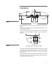
Coat the output drive shaft with a thin layer of silicon grease.
If a space ring 10A is supplied, drive it into the drive shaft until it
comes in contact with the drive shaft shoulder.
Drive the hub with cylindrical bore into the drive shaft until it comes
in contact with the drive shaft shoulder (or space ring shoulder if
supplied).
Never power the drive shaft with special washer 16 and the retain-
ing bolt 17 missing or loose.
• As for the hub with tapered bushing hole, be sure drive shaft,
bushing and hub bore are not greased. Slide the bushing into the
drive shaft to your design position.
Position the hub core over the bushing taper; insert bushing screws
through the bushing flange into the threaded hole in the hub coupling;
torque bushing screws according to the following table:
Bushing Type
Screw Torque
N·m ft·lb
Q1 and Q2 40 29
R1 and R2 40 29
Warning