


SpectraPure
SpectraPure®Inc.
480.894.5437 Call us toll-free 1.800.685.2783
2167 East Fifth St, Tempe, Arizona 85281
®
14
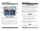
MAXCAP RO/DI™ MAINTENANCE AND REPLACEMENT
Procedure:
1. When the reading on the right-hand TDS meter (set to “IN”) displays 75%
of the reading on the left-hand TDS meter (set to “OUT”), it is time to
replace the
MAXCAP
DI
™ cartridge.
2. Follow the directions on page 8 to replace the
MAXCAP
DI
™
cartridge.
3. Make sure the DI cartridge is installed in the correct direction as marked
on the cartridge shell and be sure that the top seal is securely attached to
the top of the cartridge.
4. Tighten the cartridge housing by rotating it clockwise and hand tighten.
5. Turn on system and check for leaks.
SilicaBuster™ MAINTENANCE AND REPLACEMENT
Procedure:
1. When the reading on the right-hand TDS meter (set to “OUT”) displays
“001”, it is time to replace the SilicaBuster
™
DI cartridge.
2. Follow the directions on page 8 to replace the SilicaBuster
™
DI cartridge.
3. Make sure the DI cartridge is installed in the correct direction as marked
on the cartridge shell and be sure that the top seal is securely attached to
the top of the cartridge.
4. Tighten the cartridge housing by rotating it clockwise and hand tighten.
5. Turn on system and check for leaks.
SpectraPure®Inc
. Fax 480.894.6109 Fax us toll-free 1.877.527.7873
E-mail: spectra@spectrapure.com Visit us on the web www.spectrapure.com
11
SpectraPure
®
FLOW RESTRICTOR REMOVAL, ADJUSTMENT
AND REPLACEMENT
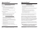
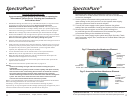
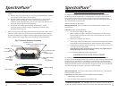
1. Locate the yellow concentrate tubing (Fig. C ). Remove the tubing from its push-fitting
at the membrane as follows:
a.) Firmly depress and hold the push-fitting collar down with your
thumbnail.
b.) While the push-fitting collar is depressed, pull the tubing straight
out of the push-fitting. Once the tubing is removed, release the collar.
2. Carefully remove the flow restrictor assembly, now visible as a plastic insert In the end
of the yellow tubing (Fig. D). You may use an object such as a dull knife to help pry the
flow restrictor insert from the end of the tubing. The entire flow restrictor (consisting
of the insert coller and thin capillary tubing) may then be gently extracted.
Note: Take care not to crush or otherwise damage the delicate capillary tubing.
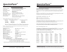
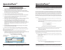
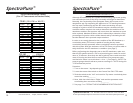
3. Refer to the Flow Restrictor Tables (Fig. B). Find the table that represents the
Flow Restrictor Assembly for the system that you have. Find the product
flow rate in the left-most column and the length of the flow restrictor in the
right-most column.
Example: If your Flow Restrictor Assembly is for a 150 GPD Membrane and
the product flow rate is 170 mL/Min, then the flow restrictor length should
be cut to 6.5 inches (16.5 mm). 170 is about halfway between 164 (7 in.)
and 175 (6 in.).
4. Using a new single-edge razor blade, carefully measure and then cut the
flow restrictor to the total length indicated.
5. Re-insert the flow restrictor assembly into the yellow tubing and firmly
re-seat the insert into the end of the yellow tubing by carefully pressing on
the insert with your thumbnail. Care should be taken not to crush or other-
wise damage the end of the capillary tubing protruding from the end of
the insert.