


!
!
Power 24 VAC, Class 2 Only
GENERAL INSTRUCTIONS:
Tools Required: .100" Flat Head Screwdriver
Phillips Head Screwdriver
Add thread
sealing tape
Be sure the bracket is properly and securely mounted
to a supporting structure capable of rigidly holding the
weight of the entire unit.
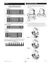
1 Using the security tool provided, open the housing by loosen-
ing the (3) captive security screws located on the housing ring
next to the lower clear dome (Figure 2).
Loosen three
security screws
holding dome
2 Install the pan/tilt unit quick-release bracket. It is recom-
mended that this be done before installing the housing.
On the next page are instructions for mounting quick-release
brackets from selected manufacturers.
3 It is recommended that the pan/tilt be installed at this time.
Connect to the quick-release bracket as shown and
secure per manufacturer directions.
4 Clean the inside of the dome, with the text-wipe provided.
Reattach the housing dome and secure the (3) captive screws.
Do not overtighten the screws. Tighten only to the point at
which the gap between the ring and the housing top closes.
ELECTRICAL SPECIFICATIONS
1
Carefully remove the housing from the packaging material.
Check to be sure all parts are present.
2 This unit includes a 1 1/2" NPT housing coupling that can
be used with a standard 1 1/2" NPT pipe. The housing can
be used with other brackets designed with 1 1/2" male pipe
threads, such as the SNCWM20 wall mount bracket.
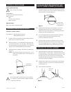
3 Attach the housing coupling to the bracket or pendant pipe
(Figure 1).
NOTE: Pipe threads should be clean and rust free. Use a
sealer (such as Tefl on™ tape or silicone sealer) on
the threads.
PREPARING PENDANT MOUNT MODEL
Figure 1
INSTALLING QUICK RELEASE BRACKET AND
PAN/TILT CAMERA ASSEMBLY (ALL MODELS)
Figure 2
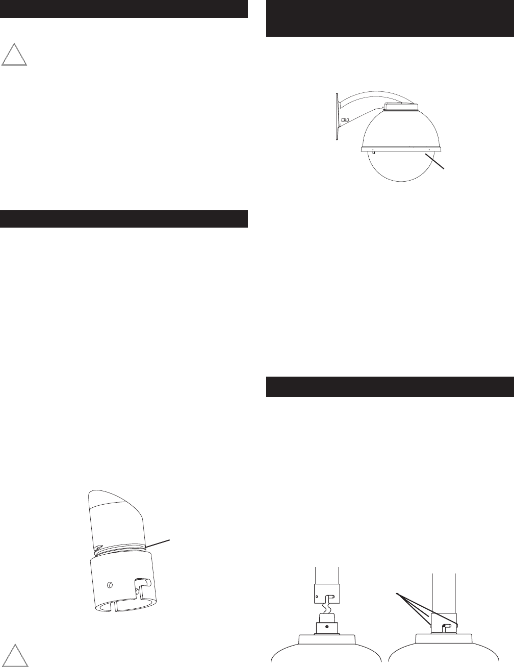
INSTALLING THE HOUSING ASSEMBLY
1
© 2003 by Sony Corporation
10/13/04
For BRCSDP12
53 watts at 24 VAC (heater and blower)
Input Connectors:
BNC
(2) screw-down connectors
RJ-45 Connector
Refer to the camera's installation guide.
1 Mount the housing assembly to the mounting bracket and
housing coupling. A safety cable is included with the housing
to temporarily hold it while making wiring connections. Loop
the safety cable over one of the set screws on the housing
coupling and make the appropriate connections using the (2)
screw-down connectors supplied.
2 Undo the safety cable and twist the housing onto the housing
coupling. Secure all (3) setscrews provided on the housing
coupling (Figure 3).
3 Clean the outside of the dome.
Twist and
Secure
Figure 3
Heater and Blower Only
Camera Power