


Extron • System 8/10 PLUS • User’s Manual • P/N 68-428-01 Rev. E
Sony LCD Compatible Installation Configuration and Connections
Sony LCD VPL-X600 Projector Configuration
Verify that the System 8/10 PLUS is already configured for the Sony LCD VPL-
X600 projector. The general setup is explained on page 3-4 and the switch
settings for the projector are repeated below.
1. Use a small screwdriver to remove the access cover from the System 8/10 PLUS
front panel. See bottom of page 3-3. The label on the back of the access cover
also has the configuration information.
__________ Before changing anything, remove the AC power cord to the System 8/10 PLUS
to verify that the main power is OFF; also turn the projector power OFF.
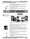
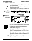
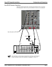
2. Set the switches as follows:
Config Model Rotary Switches Cable SW15 Settings Comm
as RS1 RS2 RS3 RS4 J2/J3 1 2 3 4 5 6 7 8 9 10 Adapter
✔ Sony VPL-X600 1 0 5 3 J2 ↑↓ ↑ ↓ ↑↓ ↓ ↓
¯
↑↓ 26-483-01
_RS5 is for RGB switching
delay. See page 3-4 for
more information on switch
functions.
3. Use a grease pencil (or other rub-off marker) to mark the space on the label next
to “Sony LCD”.
4. Locate the switcher’s Address DIP switches on the rear panel, lower right.
Unless this is part of a master/slave system, set #3 and #5 to the up position and
the others down. See illustration to the left.
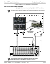
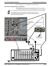
Use the illustration on the next page to do the following steps.
5. Verify that the IR Comm Adapter is configured correctly (refer to the
IR Comm
Adapter User’s Guide
). Connect the 3.5 mm male plug end of the supplied
cable into the “OUT” jack of the IR Comm Adapter. Connect the other end of the
cable into the “CONTROL S IN” port of the projector. If a hardwired remote or
host controller is being implemented, connect that device to the “IN” jack of the
IR Comm Adapter.
6. Connect the CC-50' (or CC-100') cable from the 9-pin male connector of the IR
Comm Adapter to the 15-pin HD “Projector Control” port located on the rear
panel of the System 8/10 PLUS.
______ Secure the screws on all D connectors.
7. Connect the BNC (RGBS) cables from the System 8/10 PLUS outputs to “INPUT
A” of the projector. For S-Video or Composite Video input, use the “VIDEO IN”
projector connectors.
8. Apply Main Power to the System 8/10 PLUS by connecting the power cord. The
Main Power LED should light. Apply power to the projector.
Configured For:
RS-232
3456789101
2
SW15 DIP Switch
ON
RS5 RS2
RS2
RS1
RS3
RS4
RS1
RS3 RS4
Page 2