


5
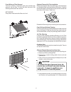
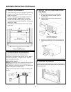
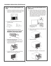
from outer case. Use both hands to grasp basepan and
pull remaining chassis from outer case.
PLASTIC FRONT
CHASSIS
BASEPAN
CLIP
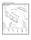
NOTE: Basepan clip is shipped in plastic bag with mounting
screw and condensate drain cup. Install clip after reinserting
chassis into outer case to prevent accidental chassis removal.
General Operating Instructions
While operation of all units is similar, controls vary slightly
from model to model. Operating Controls section shows
control panel of unit purchased and gives detailed information
about operation of controls.
Initial Start-Up and Cooling
Select the highest fan speed and set temperature control to
its coldest position. When the desired temperature is
reached, slowly move the temperature control toward a
warmer setting until the compressor shuts off. The thermo-
stat will then cycle the compressor on and off to maintain this
selected temperature. Adjust the fan speed for desired air
circulation.
Changing Airflow Direction Baffles
Airflow on unit may be diverted left or right from center by
baffles. Upward and downward air discharge is provided by
tilting louvers. Adjust baffles and tilt louvers for desired
airflow pattern.
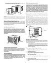
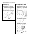
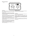
Airflow Around Unit
Check the indoor grille and outdoor louvers for obstructions to
airflow. Do not block the airflow to and from the unit. If air is
obstructed and/or deflected back into the unit, the air
conditioner’s compressor may cycle on and off rapidly. This
could damage your unit.
OUTDOOR
LOUVERS
INDOOR
GRILLE
BAFFLES
Drain Cup Installation and Use
Your air conditioner uses a system where the water removed
from the indoor air (condensate) is channeled to the outdoor
side of the unit. The outdoor fan blade has a “slinger” ring
attached to it that dips into the water and slings the water onto
the outdoor coil surface. This is the sound of water you hear
during normal operation. The water quickly evaporates on
this warm surface and improves the efficiency of your air
conditioner. In normal conditions the unit can evaporate the
water as fast as it is removed from the indoor air.
However, in very humid conditions excess amounts of water
may drip off the unit chassis. If this proves to be a problem,
install the condensate drain cup included with the unit to
route excess water where it would not be a problem (see
illustration below).
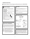
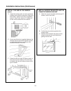
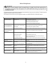
To install, remove the unit chassis from the outer case. Insert
the condensate drain cup through the recessed ½” hole on
the right side bottom flange of the outer case. Once inserted,
place a ½” diameter hose or tube on the drain cup bottom
spout. The hose allows you to route where you want the
excess water to go. Reinsert the unit chassis into the outer
case. The unit basepan overflow hole will be positioned
directly above the drain cup and will catch any water that
might run out.
1/2" Diameter
Hose
Condensate
Drain Cup
Outer Case
Switchover Thermostat Control
Emergency heat switch overrides heat pump (compressor)
and starts auxiliary electrical heater. When switch is ON,
heat pump is locked out.
• Use emergency switch only when heat pump fails to
provide adequate heat. Cause of heat pump malfunc-
tion should be determined by authorized servicer. Cost
of operating unit will increase when emergency heat
switch is engaged.
To access and engage emergency switch:
1. Remove front grille, air filter, and plastic front, as de-
scribed in Installation Instructions.
2. Remove basepan clip.
3. Slide chassis out of case about two inches.
4. Locate access hole for emergency switch above label on
right front of control box.
5. To start emergency heat, insert flathead screwdriver into
slot and turn counterclockwise until switch-stop is reached.
6. Return chassis to case.
7. Replace basepan clip, plastic front, air filter, and front
grille.