


Model 4501-XX Toxic Gas Sensor Module
• Wiring terminations clean and correct.
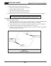
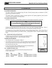
7.1.4 MOISTURE TRAPS AND RAINSHIELDS
• Conduit seals and drains installed to avoid moisture build up in electronics enclosure. Water
accumulation in sensor module enclosures is a major cause of damage and system failures - take
precautions to seal electrical conduits and provide moisture traps and drains to avoid water damage
• Rain-shields installed where applicable.
7.1.5 STANDARD VOLTAGES
• Loop voltage to be applied to the sensor module must be between 14 VDC and 30 VDC.
7.2 INSPECTION AND TROUBLESHOOTING GUIDE
The inspection and troubleshooting guide can be used to step through the system start-up and to determine
the corrective action if a fault occurs.
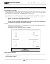
7.2.1 IF MODULE DOES NOT DISPLAY THE CORRECT PPM GAS
1. Repeat calibration procedure.
2. Remove the gas and wait for the timer to completely count down.
3. Apply Span Gas and verify that the sensor sees the correct value of the span gas after calibration.
4. If the sensor still does not respond to gas, power cycle the unit and repeat calibration.
7.2.2 IF THE MODULE DOES NOT DISPLAY THE CORRECT PPM
1. Power cycle the module.
2. Recalibrate the sensor.
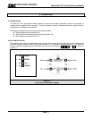
7.2.3 IF THE DISPLAY SHOWS ‘NO SENSOR’ – SENSOR FAILING
1. Power down the unit
2. Open the enclosure and unplug the sensor from the transmitter board.
3. Plug the sensor back into the transmitter board carefully and ensure a secure fit.
4. Power up the unit.
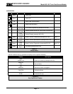
7.2.4 IF THE DISPLAY SHOWS “C” – CALIBRATION MODE
1. Complete calibration or exit to operating mode.
7.2.5 IF THE DISPLAY SHOWS “ T ” – DOWNSCALE INDICATOR
1. The reaction of the sensor to gas may, for a short period of time, result in a downscale indicator being
shown on the display.
2. If this indicator remains for a longer period of time, the sensor may need re-calibration.
7.2.6 IF THE DISPLAY SHOWS “HIGH” – UPSCALE INDICATOR
1. The concentration of the gas is outside the calibrated range.
Page: 17