


Instruction Manual
Page:
2050/2060 Gas Monitors (5/04)
3
2.0 QUICK START
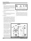
2.1 Overview
The Gas Sensor Module has been supplied factory
calibrated and ready for immediate installation and
operation. An installer familiar with installation and
operation of gas detection products can use this
section to begin immediate use of the monitor.
2.2 Wiring
Each module requires four-conductor wiring (two
wires for power and two wires for the signal).
2.2.1. Model 2050-2060 Series
The Model 2050-2060 series are designed to
mount on any indoor vertical surface. Mount
the monitor in the desired location.
- The installation must meet any hazard-
ous environmental codes for AC/DC elec-
trical instrumentation.
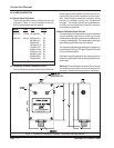
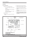
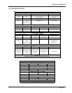
2.2.2 Wiring Connection
Terminal positions on the electronics board are
as follows:
2.2.3 Start-up & Operation
To begin operation of the Gas Sensor Module
provide 9 - 24 VDC from a regulated power
supply such as one of the Sierra Monitor Alarm
Panels, 2102-XX. Each time the sensor mod-
ule is powered up it will perform a warm-up for
2 - 60 minutes.
During warm-up the monitor will, first, cycle
through safe/alarm/safe condition at one hertz.
This will be followed by a short period of continu-
ous alarm before warm-up is completed.
2.2.4 Configuration
The default configuration for each module is to
operate with a buzzer and a normally operating
open (NOO) relay. The user can change this con-
figuration using the jumpers provided. Refer to
table 6.2.
Terminal Function
TB1-1 + VDC (9 – 24)
TB1-2 GND (0VDC)
TB2-1 Relay NC (Normally Closed) or
Output to Model 2102 Safe
TB2-2 Relay Common
TB2-3 Relay NO (Normally Open) or
Output to Model 2102 Alarm
Table 2.1