


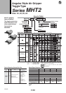
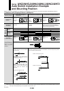
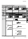


Various auto switch applications are possible through different combinations of auto switch quantities and detecting positions.
1) Detection when Gripping Exterior of Workpiece
Detection example
Detection
combinations
One auto
switch
Two auto
switches
How to determine
auto switch
installation position
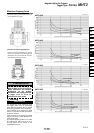
At no pressure or low
pressure, connect the
switch to a power
supply, and follow the
directions.
1. Confirmation of fingers in
reset position
2. Confirmation of workpiece held 3. Confirmation of workpiece released
Position of
fingers fully
opened
Position
when
gripping
workpiece
Position of
fingers fully
closed
Switch turned on when fingers return.
(Light ON)
Switch turned on when gripping a
workpiece.
(Light ON)
When a workpiece is held (Normal operation):
Switch to turn OFF (Light not illuminating)
When a workpiece is not held (Abnormal operation):
Switch to turn ON (Light illuminating)
Step 1)
Fully open the
fingers.
Step 1)
Position
fingers for
gripping a
workpiece.
Step 1)
Fully close the
fingers.
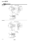
Step 2) Insert the auto switch into the switch installation groove in the direction shown in the following drawing.
Step 3) Slide the auto switch in the
direction of the arrow until the indicator
light illuminates.
Step 4) Slide the auto switch further in
the direction of the arrow until the
indicator light goes out.
Step 5) Move the auto switch in the
opposite direction and fasten it at a
position 0.3 to 0.5 mm beyond the
position where the indicator light
illuminates.
Step 3) Slide the auto switch in the direction of the arrow until the light illuminates and
fasten it at a position 0.3 to 0.5 mm in the direction of the arrow beyond the position
where the indicator light illuminates.
Position where light turns ON
Position to be
secured
Note 1) It is recommended that gripping of a workpiece be performed close to the center of the finger stroke.
Note 2) When holding a workpiece close at the end of open/close stroke of fingers, detecting performance of the combinations listed in the above
table may be limited, depending on the hysteresis of an auto switch, etc.
Position where light turns ON
Position to be secured
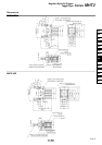
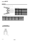
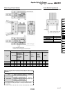
Series MHZ2/MHZJ2/MHK2/MHKL2/MHC2/MHT2
Auto Switch Installation Example
and Mounting Position
0.3 to 0.5 mm
0.3 to 0.5 mm
Ȝ
Ȝ
Ȝ
ȜȜ
ȜȜ
Ȝ Ȝ
Position to be
detected
Operation of
auto switch
12-12-2