


VI
CTORY
II V
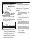
HS Models
BOILER ROOM AIR SUPPLY AND VENTILATION
An ample supply of air is required for combustion and venti-
l
ation. When buildings are insulated, caulked and weather-
stripped, now or later on, direct openings to outside may be
required and should be provided. If the boiler is not near an
o
utside wall, air may be ducted to it from outside wall openings.
Provisions for combustion and ventilation air must be made
in accordance with section 5.3, Air for Combustion and Venti-
lation, of the National Fuel Gas Code, ANSI Z223.1-latest
e
dition, or applicable provisions of the local building codes.
The following recommendation applies to buildings of ener-
gy-saving construction, fully caulked and weatherstripped.
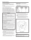
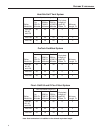
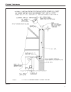
INSTALLATION IN ENCLOSED BOILER ROOM REQUIRES
TWO UNOBSTRUCTED OPENINGS FOR PASSAGE OF
AIR INTO THE BOILER ROOM:
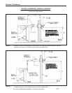
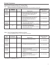
1.
Air drawn horizontally from outdoors DIRECTLY
through an outside wall;
one louvered opening near
the floor and one louvered opening near the ceiling, each
opening with a minimum FREE air passage area of 1
square inch per 4000 Btuh of total appliances’ input.
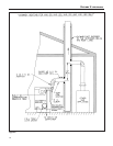
2.
Air drawn horizontally through HORIZONTAL
DUCTS; one opening near the floor and one opening
near the ceiling, each opening with a minimum FREE air
passage area of
1 square inch per 2000 Btuh of total
appliances’ input.
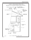
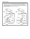
3.
Air drawn VERTICALLY from outdoors; one opening at
the floor and one opening at the ceiling, each opening
with a minimum FREE air passage area of
1 square
inch per 4000 Btuh of total appliances’ input.
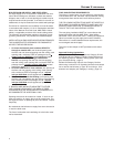
4. Air drawn from inside the building; one opening near
the floor and one opening near the ceiling, each opening
with a minimum FREE air passage area of
1 square
inch per 1000 Btuh of total appliances’ input.
IF BOILERS ARE INSTALLED ADJACENT TO OTHER
FUEL BURNING EQUIPMENT, THE AREA OF FREE
OPENINGS MUST BE APPROPRIATELY INCREASED TO
ACCOMMODATE THE ADDITIONAL LOAD.
Openings must never be reduced or closed. If doors or win-
dows are used for air supply, they must be locked open. Pro-
tect against closure of openings by snow and debris. Inspect
frequently.
No mechanical draft exhaust or supply fans are to be used in
or near the boiler area.
The flow of combustion and ventilating air to the boiler must
not be obstructed.
FLUE GAS VENTING REQUIREMENTS
T
he Victory
I
I
s
eries boiler is a high efficiency, mechanically
i
nduced draft boiler and, therefore, requires different venting
arrangements than natural draft, lower efficiency boilers.
T
HE FOLLOWING INSTRUCTIONS MUST BE CAREFULLY
READ AND FOLLOWED IN ORDER TO AVOID ANY HAZ-
ARDOUS CONDITIONS DUE TO IMPROPER INSTALLA-
TION OF THE FLUE GAS VENTING SYSTEM.
The vent piping installation MUST be in accordance with
these instructions and with ANSI Z223.1-latest edition
NATIONAL FUEL GAS CODE, Part 7, Venting of Equipment.
O
ther local codes may also apply and must be followed.
Where there is a conflict between these requirements, the
more stringent case shall apply.
The use of a vent damper is NOT permitted on this boiler
series.
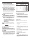
Approved Venting Applications
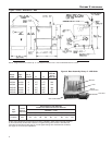
Victory II model VHS-90 through 180 are Category III and
VHS-30 and 60 are Category
II boilers, these boilers must
be vented by proper 3" diameter venting system (see Cate-
gory
II and III venting - page 5).
Models VHS-90 through 180 are also Category
I boilers
when using a minimum of 5" diameter connector and vented
into a natural draft chimney or Type “B” vent using a 3"x5"
diameter vent adapter (see Category
I venting - page 10).
4