


Installation 4
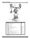
DESCRIPTION
This Submersible Sump Pump is designed for home
sumps. The unit is equipped with a 3-prong grounding-
type power cord. The shaded pole motor is oil filled and
sealed for cooler running. Sleeve bearing on the motor
shaft never needs lubrication. Automatic reset thermal
protection.
NOTE: This unit is not designed for applications involving
salt water or brine! Use with salt water or brine will void
warranty.
Pump water only with this pump.
SPECIFICATIONS
Power Supply Required................................115V, 60HZ.
Liquid Temperature Range........130° F (55° C Maximum)
Individual Branch Circuit Required.................15.0 Amps
Motor Full Load (maximum)............................12.0 Amps
Discharge Pipe Size........................................1-1/2" NPT
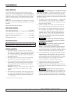
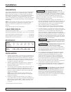
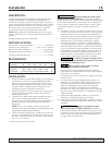
PERFORMANCE
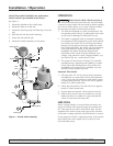
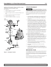
INSTALLATION
1. Install the pump in a sump pit with a minimum
diameter of 10" (254mm). The sump depth should be
14" minimum)(356mm). Construct the sump pit of
tile, concrete, steel or plastic. Check local codes for
approved materials.
2. Install the pump in the pit so the switch operating
mechanism has maximum possible clearance.
3. The pump should not be installed on clay, earth or
sand surfaces. Clean the sump pit of small stones
and gravel which could clog the pump. Keep the
pump inlet screen clear.
NOTICE: Do not use ordinary pipe joint compound
on plastic pipe. Pipe joint compound can attack
plastics.
4. Install discharge plumbing. When using rigid pipe,
use plastic pipe. Wrap the thread with Teflon
TM
tape.
Screw the pipe into the the pump hand tight plus
1 – 1-1/2 turns.
TM
E.I. DuPont DeNemours and Company, Corporation.
Risk of flooding. Can cause personal injury
or property damage. If a flexible discharge hose is used,
make sure the pump is secured in the sump to prevent
movement. Failure to secure the pump may allow pump
movement, switch interfere e and prevent the pump from
starting or stopping.
5. To reduce motor noise and vibrations, a short length
of rubber hose (1-7/8" (47.6mm) ID, e.g. radiator
hose) can be connected into the discharge line near
the pump using clamps.
6. Install an inline check valve to prevent backward
flow through the pump when the pump shuts off.
7. Power Supply: The pump is designed for 115V.,60
Hz., operation and requires a 15 amp individual
branch circuit. Both the pump and the switch are
supplied with a 3-wire cord with grounding-type
plug. The switch plug is inserted directly into the
outlet and the pump plug inserts into the opposite
end of the switch plug.
To reduce risk of electric shock, be
certain that it is connected to properly grounded,
grounding-type receptacle.
Never connect green (or green and
yellow) wire in cord to a live terminal!
Where a 2-prong wall receptacle is encountered, it
must be replaced with properly grounded 3-prong
receptacle installed in accordance with the National
Electrical Code and local codes and ordinances.
8. If the discharge line is exposed to outside sub-freez-
ing temperatures, that portion of the line must be
installed so any water remaining the pipe will drain
to the outfall by gravity. Failure to do this can cause
the water trapped in the discharge line to freeze
which could result in damage to the pump.
9. After the piping and the check valve have been
installed, the unit is ready for operation.
10. Check the operation by filling the sump with water
and observing the pump operation through one com-
plete cycle.
Flood hazard. Can cause personal
injury or property damage. Check the operation of
the pump by observing through one complete cycle.
Failure to make this operational check may lead to
improper operation, premature failure, and flooding.
For parts or assistance, call Simer Customer Service at 1-800-468-7867 / 1-800-546-7867
Total Lift in Feet 0' 5' 10' 15' 20' 32’
Capacity in GPH 4500 4080 3480 2880 2380 0