


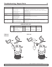
For parts or assistance, call Simer Customer Service at 1-800-468-7867 / 1-800-546-7867
General Information / Installation / Operation 3
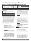
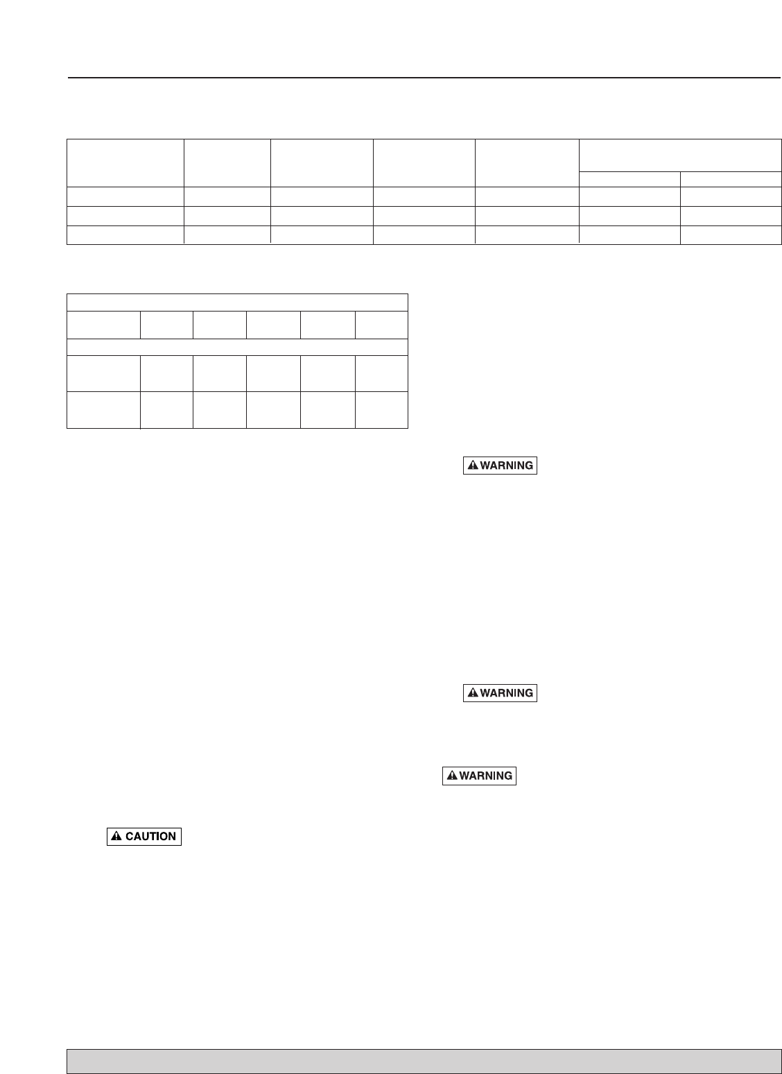
PERFORMANCE
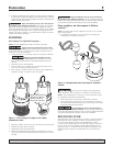
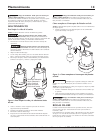
INSTALLATION
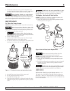
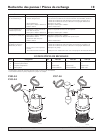
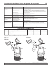
1. Install tethered switch models in a sump pit with a mini-
mum diameter of 14" (356mm). Install vertical switch mod-
els in a sump pit with a minimum diameter of 11" (280mm).
Construct the sump pit of tile, concrete, steel or plastic.
Check the local codes for approved materials.
The pump should not be installed on clay, earth or sand sur-
faces. Clean the sump pit of small stones and gravel which
could clog the pump. Keep the pump suction housing clear
of debris.
2. Install the pump in the pit so the switch operating mecha-
nism has maximum possible clearance.
3. Install an in-line check valve to prevent flow backwards
through the pump when the pump shuts off.
4. Install the discharge plumbing.
A. When using rigid pipe, use plastic pipe. Wrap the dis-
charge pipe thread with Teflon
TM
tape. Screw the pipe
into the pump discharge port hand tight +1 – 1-1/2 turns.
NOTICE: Do not use ordinary pipe joint compound on
plastic pipe. Pipe joint compound can attack plastics.
NOTICE: Thread the discharge pipe into the pump body
carefully to avoid stripping or crossing threads.
B. If a flexible discharge hose is used, make sure the pump
is secured in the sump to prevent movement. Do not use
a flexible discharge pipe in any permanent installation.
Risk of flooding. Can cause personal
injury or property damage. Failure to secure pump may
allow pump movement, switch interference and prevent
pump from starting or stopping.
NOTICE: The discharge piping should be as short as pos-
sible to reduce pipe friction losses. Discharge pipe diam-
eter should be equal to or larger than the discharge size
of the pump. Smaller pipe diameters will restrict the
capacity of the pump and reduce pump performance.
C. Secure the discharge line before starting the pump.
To reduce motor noise and vibrations, a short length of
rubber hose (e.g. radiator hose) can be connected into
the discharge line near the pump using suitable clamps.
If the pump discharge line is exposed to outside sub-
freezing atmosphere, the portion of the line exposed
must be installed so any water remaining in the pipe will
drain to the outfall by gravity. Failure to do this can
cause any water trapped in the discharge line to freeze
which could result in damage to pump.
5. Power Supply: This pump is designed for 115 V., 60 Hz.,
operation and requires a minimum 15 amp individual
branch circuit. Both the pump and switch are supplied with
3-wire cord sets with grounding-type plugs. The switch plug
is inserted directly into the outlet and the pump plug inserts
into the opposite end of switch plug.
Hazardous voltage. Can shock, burn or
cause death. Pump is supplied with a grounding conductor
and grounding-type attachment plug. To reduce the risk of
electric shock, be certain that it is connected only to a prop-
erly grounded, grounding type receptacle such as a ground-
ed water pipe or a properly grounded metallic raceway or
ground wire system. Ground terminal on pump cord plug is
provided for your protection. DO NOT REMOVE!
A ground fault circuit interrupter is recommended for use
with any electrical appliance submerged in water. For instal-
lation of such a circuit, consult a licensed electrician.
6. After the piping and the check valve (if needed) have been
installed, the unit is ready for operation
7. Check the operation by filling the sump with water and
observing pump operation through one complete cycle.
Risk of flooding. Can cause personal injury
and/or property damage. Failure to make this operational
check may lead to flooding and premature failure.
OPERATION
Risk of electric shock. Shock can burn or kill.
Do not handle a pump or pump motor with wet hands or
when standing on wet or damp surface, or in water.
1. Keep the pump inlet screen clear.
2. The shaft seal depends on water for lubrication. Do not
operate the pump unless it is submerged in water as the
seal may be damaged if the pump is allowed to run dry.
3. The motor is equipped with an automatic reset thermal
protector. If the temperature in the motor should rise undu-
ly, the switch will cut off all of the power before any dam-
age can be done to the motor. When the motor has cooled
sufficiently, the switch will reset automatically and restart
the motor. If the protector trips repeatedly, the pump
should be removed and checked for the cause of the diffi-
culty. Low voltage, long extension cords, a clogged
impeller, very low head or lift, etc., could cause cycling.
Refer to the Troubleshooting Chart on Page 5 for additional
information.
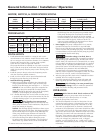
Individual Switch Setting
Model Max. Branch Circuit Cord in inches (mm)
Number HP Load Amps Required (Amps) Length
On Off
2905-04 1/4 6.0 15 8’ 10” (254) 3” (76)
2955-04 1/3 10.0 15 8’ 11” (279) 4” (102)
2957-04 1/3 10.0 15 8’ 7-1/2” (191) 2-1/2” (64)
MOTOR, SWITCH, & CORD SPECIFICATIONS
GPM (LPM) AT TOTAL FEET (m)
510152025
Model (1.5m) (3m) (4.6m) (6.1m) (7.6m)
CAPACITY GALLONS(L)/HOUR
2905-04
1,170 1,020 810 510 0
(4,429) (3,840) (3,066) (1,931) (0)
2955-04 1,740 1,620 1,260 720 60
2957-04 (6,600) (6,120) (4,740) (2,700) (240)
TM
E.I. DuPont de Nemours and Company Corporation.