


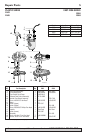
For parts or assistance, call Simer Customer Service at 1-800-468-7867 / 1-800-546-7867
Installation and Operation 3
To reduce risk of electric
shock, pull plug before ser-
vicing. This pump has not been investigated for
use in swimming pool areas. Pump is supplied
with a grounding conductor and grounding-type
attachment plug. Be sure it is connected only to
a properly grounded grounding-type receptacle.
Where a 2-prong wall receptacle is encoun-
tered, it must be replaced with properly
grounded 3-prong receptacle installed in accor-
dance with codes and ordinances that apply.
13. All wiring should be performed by a qualified
electrician.
14. Make certain power source conforms to require-
ments of your equipment.
15. Protect electrical cord from sharp objects, hot
surfaces, oil, and chemicals. Avoid kinking cord.
Replace or repair damaged or worn cords imme-
diately.
16. Do not touch an operating motor. Modern motors
can operate at high temperatures.
17. Do not handle pump or pump motor with wet
hands or when standing on wet or damp surface,
or in water.
Hazardous voltage can shock,
burn or kill. If your basement
has water or moisture on floor, do not walk on wet
area until all power has been turned off. If shut-off
box is in basement, call electric company or hydro
authority to shut-off service to house, or call your
local fire department for instructions. Remove
pump and repair or replace. Failure to follow this
warning can result in fatal electrical shock.
Do not lift pump by power cord.
FLOAT SWITCH INSTALLATION
Models equipped with vertical switches require some
assembly. See the Switch Assembly instructions on
Page 4. Models with tethered float switches are
ready for use.
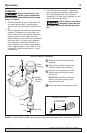
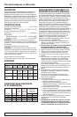
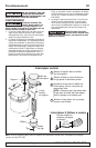
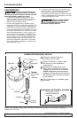
INSTALLATION
1. Install pump in sump pit with minimum diameter
of 10" (254mm) for models equipped with verti-
cal switches and 14" (356mm) for tethered float
switch models. Sump depth should be 16"
(406mm) for tethered models and 10” (254mm)
for vertically switched models. Construct sump
pit of tile, concrete, steel or plastic. Check local
codes for approved materials and for proper
installation.
2. Install pump in pit so that switch operating
mechanism has maximum possible clearance.
3. Pump should not be installed on clay, earth or
sand surfaces. Clean sump pit of small stones
and gravel which could clog pump. Keep pump
inlet screen clear.
NOTICE: Do not use ordinary pipe joint com-
pound on plastic pipe. Pipe joint compound can
attack plastics.
4. Install discharge plumbing. Use rigid plastic pipe
and wrap threads with Teflon
TM
tape. Screw pipe
into pump hand tight plus 1-1/2 turns.
Risk of flooding. If a flexible
discharge hose is used,
make sure pump is secured in sump to prevent
movement. Failure to secure pump may allow
pump movement, switch interference and pre-
vent pump from starting or stopping.
5. To reduce motor noise and vibrations, a short
length of rubber hose (1-7/8" (47.6mm) I.D., e.g.
radiator hose) can be connected into discharge
line near pump using suitable clamps.
6. Install an in-line check valve or an in-pump check
valve to prevent flow backwards through pump
when pump shuts off.
NOTICE: If your check valve is not equipped with
an air bleed hole to prevent airlocking pump, drill
a 1/8" (3.2 mm) hole in discharge pipe just above
where the discharge pipe screws into the pump
discharge. Be sure the hole is below the waterline
and the check valve to prevent air locks.
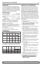
7. Power Supply: Pump is designed for 115 V., 60
Hz., operation and requires a minimum 15 amp
individual branch circuit. Both pump and switch
are supplied with 3-wire cord sets with ground-
ing-type plugs. Switch plug is inserted directly
into outlet and pump plug inserts into opposite
end of switch plug.
Pump should always be elec-
trically grounded to a suit-
able electrical ground such as a grounded
water pipe or a properly grounded metallic
raceway, or ground wire system. Do not cut off
round ground pin.
8. If pump discharge line is exposed to outside sub-
freezing atmosphere, portion of line exposed
must be installed so any water remaining in pipe
will drain to the outfall by gravity. Failure to do
this can cause water trapped in discharge to
freeze which could result in damage to pump.
9. After piping, check valve and float switch have
been installed, the unit is ready for operation.
10. Check the pump operation by filling sump with
water and observing pump operation through one
complete cycle. For switch settings see the Electrical
and Switch Specifications chart on Page 2.
Failure to make this opera-
tional check may lead to
improper operation, premature failure, and
flooding.
TM
E.I.DuPont De Nemours and Company Corporation, Delaware.