Sigma K1000 Series 1, 2, 4 & 6 Zone Fire Control Panels Operation and Maintenance Manual
Page 6 of 10
Smoke Detection Circuits
7.1 One to six smoke detection circuits are provided and supply 28 Volts ( + 5%) for the
operation of trigger devices, (smoke detectors or heat detectors). Terminals for the
smoke detection circuits are labelled Z1+ and Z1- to Z6+ and Z6- for positive and
negative connections respectively. It is important to observe the polarity of these
connections for correct operation of the system.
7.2 A 6K8 end of line resistor must be fitted to the last device on the smoke detection
circuit for correct operation of the monitoring functions. Alternatively for greater system
integrity a line continuity monitoring unit (LCMU) may be fitted.
Sounder Circuits
8.1 Two sounder circuits outputs are provided and are labelled (S1 +&-) &( S2 + &-).
These outputs will operate together upon activation of a smoke detection zone, opera-
tion of the evacuate switch or the remote Alarm input. Each sounder circuit is pro-
tected by a 500mA fuse.
8.2 Both outputs are monitored against open and short circuit faults in the field wiring.
Any such faults are annunciated by the front panel system fault indicator immediately.
8.5 The sounder circuit is normally fitted with a 20K end of line monitoring resistor.
Fault VFCO Contacts
9.1 Volt free contacts are provided for remote signalling or plant shutdown on the occurrence
of any fault condition.
Fire VFCO Contacts
10.1 Volt free contacts are provided for remote signalling or plant shut down on the
occurrence of any fire condition or evacuate condition.
10.2 All contacts are rated at 30V DC 1 Amp maximum and should under no circumstances
be used to switch greater voltages or currents (see annex 3).
INTERNAL CONTROLS -
Continued
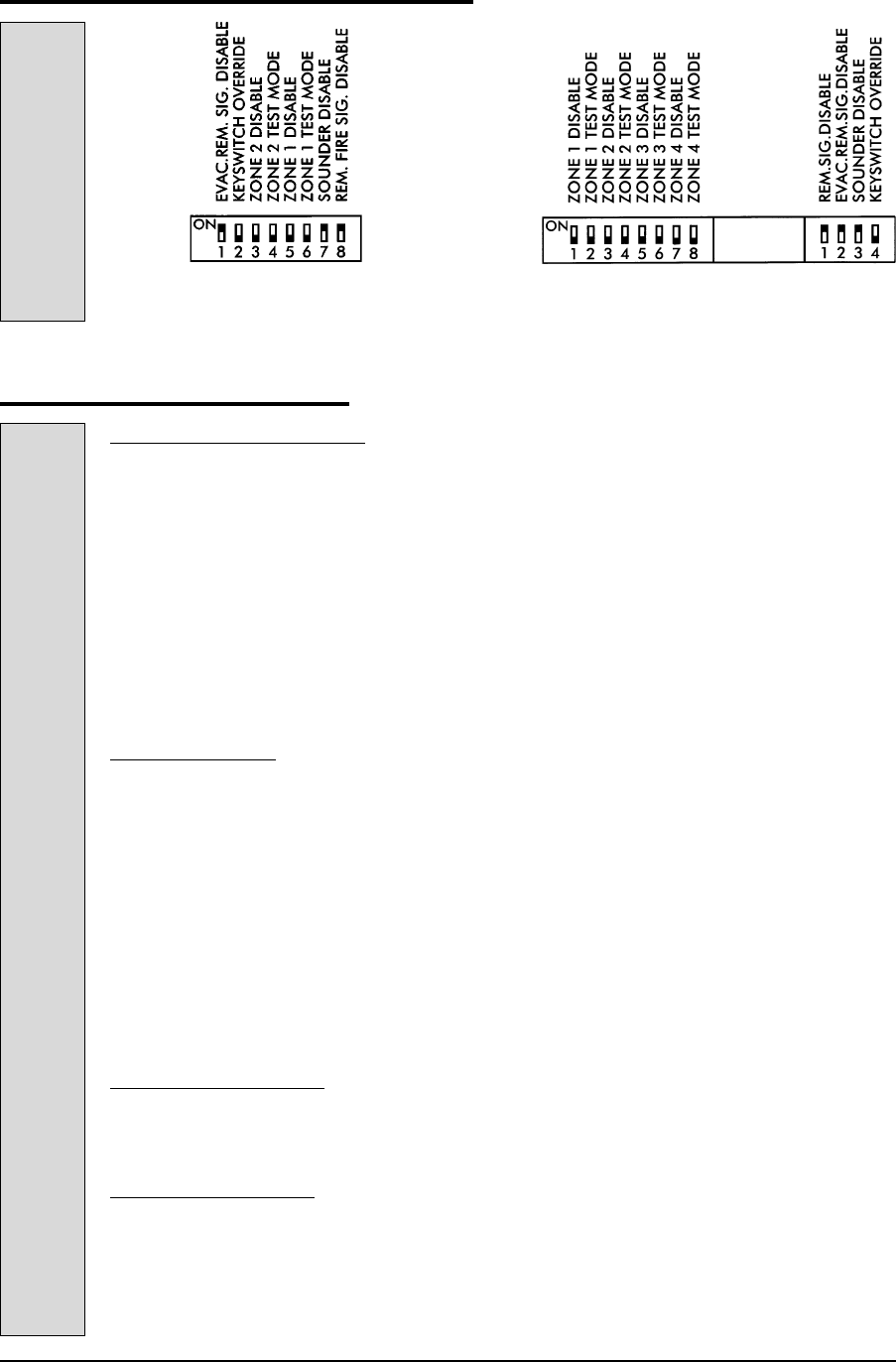
Two zone Sigma
Normal switch positions
Four zone Sigma
Normal switch positions
TERMINAL FUNCTIONS


