AYXP7FR
3 – 13
[8] TROUBLESHOOTING GUIDE
1. Self-Diagnosis Function and Display Mode
To call out the content of the self-diagnosis memory, hold down the emergency operation button for more than 5 seconds when the indoor unit is not
operating.
• The number of indications displayed by the LEDs on the outdoor unit differs from that for the 2001 cooling unit models (for detailed display of mal-
function information).
The display of malfunction No. differs from that of the 2001 cooling unit models. To show detailed malfunction information, two types of numbers
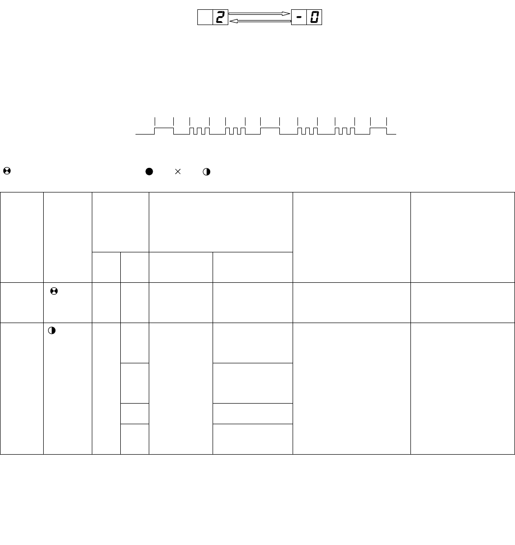
flash alternately. (example: "21" ←→ "-0")
1) The content of the self-diagnosis memory can be called out and displayed on the seven-segment display section on the indoor unit. (The error
data cannot be called out for display by the LED on the outdoor unit.)
2) If the power cord is unplugged from the AC outlet or the circuit breaker is turned off, the self-diagnosis memory loses the stored data.
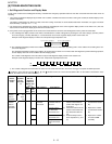
a) The self-diagnosis display function of the indoor unit indicates the content of diagnosis by showing the error main category (number) and the
error sub-category (-number) alternately in 1-second intervals on the seven-segment display section of the indoor unit.
Example of self-diagnosis display on indoor unit: Compressor high-temperature error
b) The self-diagnosis display function of the outdoor unit indicates the error information by flashing LED1 on the outdoor unit according to the con-
tent of self-diagnosis.
The self-diagnosis display function of the outdoor unit is active only for about 3 to 10 minutes after self-diagnosis is performed during operation,
and the display returns to normal condition after this display period.
The content of self-diagnosis cannot be called out by the self-diagnosis display function of the outdoor unit.
Example of self-diagnosis display on outdoor unit: Compressor high-temperature error
c) The content of diagnosis is transferred to the indoor unit via serial communication, but it does not trigger a complete shutdown operation.
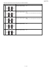
: Flashes in 2-sec intervals (normal), : On, : Off, : Flashes 3 times in 0.2-sec intervals (When LED1 on the outdoor unit flashes in 2-sec
intervals, the outdoor unit is in normal condition.)
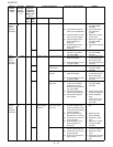
Status of
indoor/
outdoor
units
Indication
by LED1
on out-
door unit
*2
Malfunction
No. dis-
played on
main unit
display sec-
tion *1
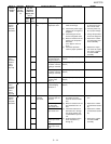
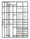
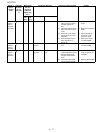
Content of diagnosis Inspection location/method Remedy
Main
cate-
gory
Sub-
cate-
gory
Main category Sub-category
Indoor/
outdoor
units in
operation
Nor-
mal
flash-
ing
00 Normal – –
Indoor/
outdoor
units in
complete
shutdown
1 time 1 -0 Outdoor unit
thermistor
short-circuit
Heat exchanger
thermistor short-cir-
cuit error
(1) Measure resistance of the
outdoor unit thermistors.
(TH2 to TH5: Approx. 4.4
kΩ at 25°C)
(1) Replace the outdoor
unit thermistor assem-
bly.
-1 Outside tempera-
ture thermistor
short-circuit error
(2) Check the lead wire of the
outdoor unit thermistor for
torn sheath and short-cir-
cuit.
(2) Replace the outdoor
unit thermistor assem-
bly.
-2 Suction thermistor
short-circuit error
(3) No abnormality found in
above inspections (1) and
(2).
(3) Replace the outdoor
unit control PWB
assembly.
-3 2-way valve ther-
mistor short-circuit
error
'TTQTOCKPECVGIQT[ 'TTQTUWDECVGIQT[
1sec 1sec 1sec 1 sec 1sec1sec0.6sec 0.6sec0.6sec 0.6sec 1sec
ON
OFF
1sec 1sec


