


AYXP7FR
3 – 16
Indoor/
outdoor
units in
complete
shutdown
11
times
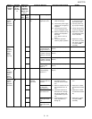
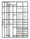
11 -0 Outdoor unit DC
fan
Outdoor unit DC fan
rotation error
(1) Check connector CN3 of
the outdoor unit DC fan
motor for secure installa-
tion.
(1) Correct the installa-
tion.
(2) Check the outdoor unit fan
motor for proper rotation.
(2) Replace the outdoor
unit fan motor.
(3) Check fuse FU3. (3) Replace the outdoor
unit control PWB
assembly.
(4) Outdoor unit control PWB (4) Replace the outdoor
unit control PWB
assembly.
Indoor/
outdoor
units in
complete
shutdown
13
times
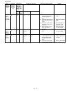
13 -0 DC compressor Compressor startup
error
(1) Check the colors (red,
white, orange) of the com-
pressor cords for proper
connection. (PWB side,
compressor side)
(1) Correct the installa-
tion.
(U: Red, V: White, W:
Orange)
-1 Compressor rota-
tion error
(120° energizing
error)
(2) Check if the IPM terminal
resistance values are uni-
form.
(2) Replace the outdoor
unit control PWB
assembly.
(3) No abnormality found in
above inspections (1) and
(2).
(3) Replace the outdoor
unit control PWB
assembly.
(4) No abnormality found in
above inspections (1)
through (3).
(4) Replace the compres-
sor.
Indoor/
outdoor
units in
complete
shutdown
14
times
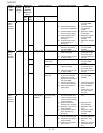
14 -0 Outdoor unit
PAM
PAM over voltage
error
Compressor rota-
tion error
(1) Check the AC power sup-
ply voltage for fluctuation.
(1) Connect stable power
supply.
(2) No abnormality found in
above inspection (1).
(2) Replace the outdoor
unit control PWB
assembly.
Indoor/
outdoor
units in
operation
-1 PAM clock error (1) Check the PAM clock for
proper input.
(1) Replace the outdoor
unit control PWB
assembly.
Indoor
unit in
operation
Outdoor
unit in
complete
shutdown
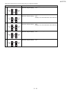
17 -0 Wires between
units
Serial open-circuit (1) Check the wires between
units.
(1) Connect stable power
supply.
(2) Check voltage between
Nos. 1 and 2 on the
indoor/outdoor unit termi-
nal boards.
(2) Replace the outdoor
unit control PCB
assembly.
Outdoor unit does
not turn on due to
erroneous wiring
(1) Check the wires between
units.
(1) Correct the wiring.
(2) Check the outdoor unit
fuse.
(2) Replace the fuse/out-
door unit control PCB
assembly.
(3) Check 15-V, 13-V and 5-V
voltages on the PWB.
Check resistance between
IPM terminals.
(3) Replace the outdoor
unit control PCB
assembly.
(4) Check pins No. 5 and 7 of
connector CN3 of the out-
door unit fan motor for
short-circuit.
(4) Replace the outdoor
unit fan motor.
(5) Outdoor unit control PCB (5) Replace the outdoor
unit control PCB
board.
18 -0 Serial short-circuit (1) Check the wires between
units.
(1) Correct the wiring.
-1 Serial erroneous wir-
ing
(1) Check the wires between
units.
(1) Correct the wiring.
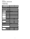
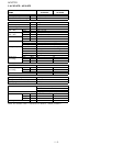
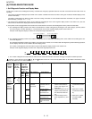
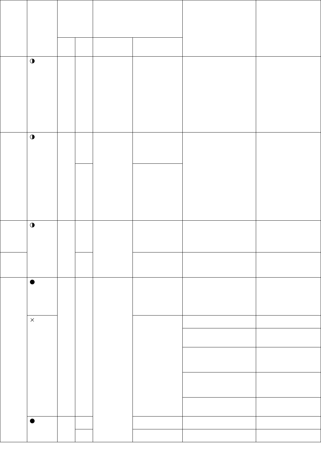
Status of
indoor/
outdoor
units
Indication
by LED1
on out-
door unit
*2
Malfunction
No. dis-
played on
main unit
display sec-
tion *1
Content of diagnosis Inspection location/method Remedy
Main
cate-
gory
Sub-
cate-
gory
Main category Sub-category