


Printed in China
TINS-B760WJZZ
05P01-CH-NM
Lens mounting screws
2
1
Positioning pin
Lens cap (back)
Motor section
Lens mount
2
1
Positioning pin
Guide
hole
Cable connector
3
Ribs
Lens cover
Tabs
10
1211
9
7
8
13 14
Positioning pin
a
mark
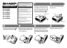
Remove the lens mounting
screws.
Rotate the replacement lens 90
degrees in the direction shown
by the arrow (
11
11
1), align the posi-
tioning pin with the guide hole
(
22
22
2), tighten the lens mounting
screws and then connect the
cable connector (
33
33
3).
Pull out the lens towards you and
then take out the lens (
22
22
2) by ro-
tating it 90 degrees (
11
11
1) in the di-
rection shown by the arrow.
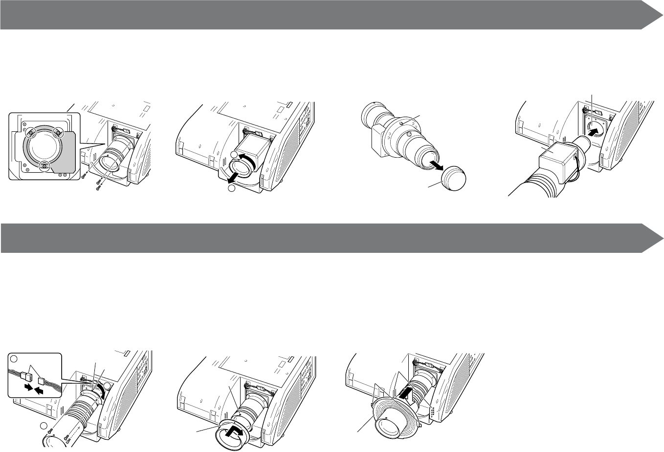
(When the lens being attached is the AN-
PH30EZ (XG-PH50X standard lens))
Attach the lens ring.
• Align the a mark on the lens ring with the
positioning pin on the lens (silver pin), in-
sert the lens ring all the way to the back
and then rotate in the direction of the ar-
row.
Remove the lens cap (on the
back) from the replacement lens.
• This explanation uses the example of the
AN-PH10EX.
Attach the lens cover.
• Insert the lens cover while spreading apart
the ring section (made of rubber), and then
attach the tabs to the ribs.
Insert the replacement lens into
the lens mount with the motor
section facing up.
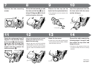
Connect the cable connector by
following steps 1 through 3, and
then attach the top cover and
lamp unit cover.
• The power of the projector will not come
on unless the lamp unit cover is securely
attached.