


Digital Access Keypad Manual
SECO-LARM U.S.A., Inc.
Digital Access Keypad Manual
OUTPUT 1
EG
INN.C.
N.O.
(+)
(--)
Door
Sens
GREEN LED
OUTPUT 3
O/P 1 Disable
(for DC
use only)
Egress button (inside the
protected premises)
GREEN LED
RED LED
RED LED
(+)
N.C.
N.O.
12~24V AC/DC
C.
(--)
(+)
(--)
(+)
1 2 3 4 5 6 7 8 9 10 11 12 13 14 15 16
12VDC
power
supply
+
--
Electric
Lock
Diode
1N4004
Cathode
N.O.
Additional egress buttons
can be connected in
parallel as needed
N.O.
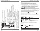
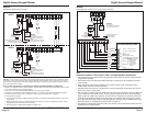
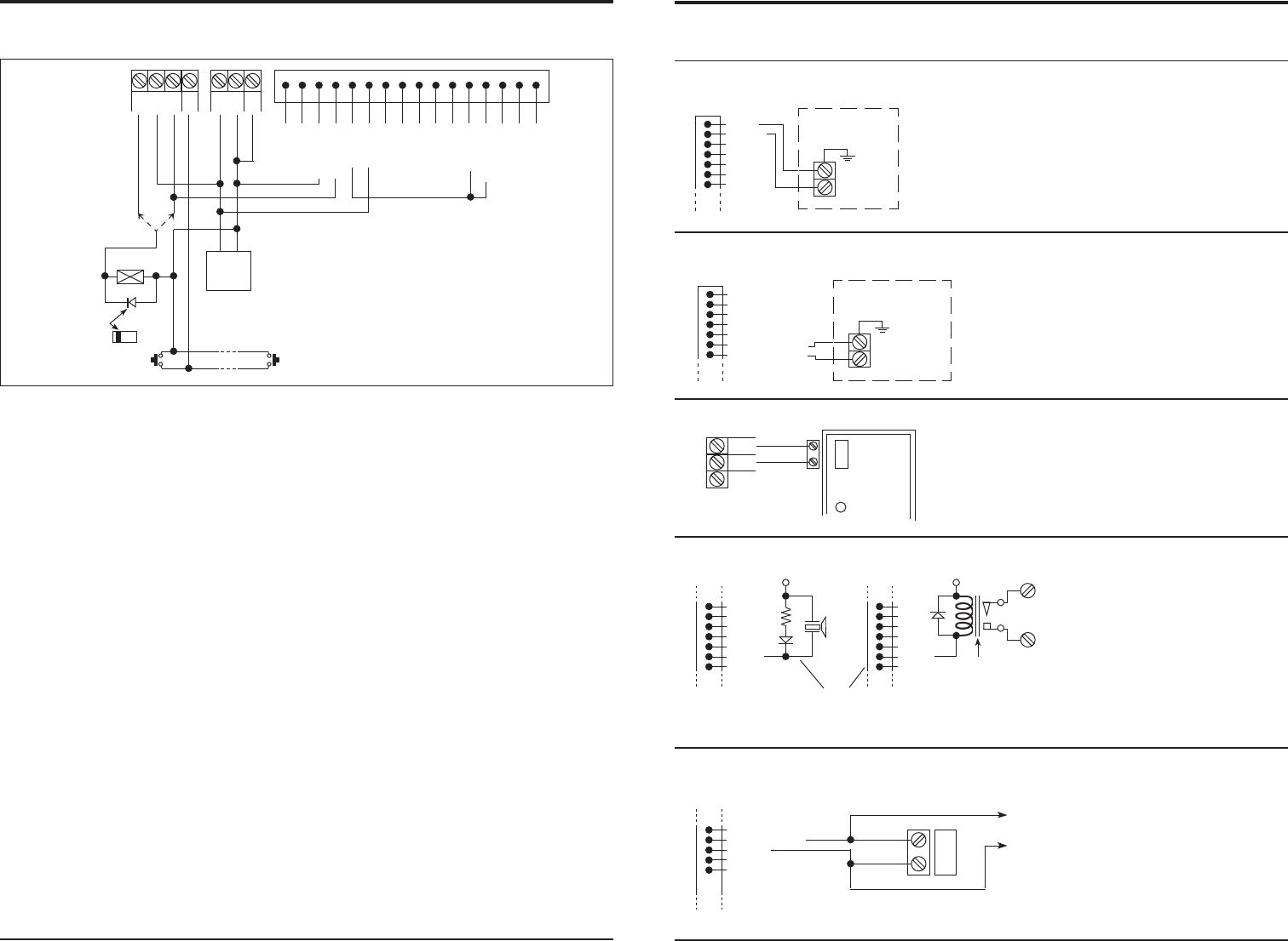
REMARKS:
Output relay #1
N.O. output for fail-secure lock.
N.C. output for fail-safe lock.
LEDs:
Each LED requires a 1.5K-Ohm
series resistor for 24V operation.
Note:
• Connect a 1N4004 diode as close as possible to and in parallel with the DC-
powered electromagnetic or electric lock. This absorbs possible electromagnetic
interference to prevent operation of the lock from damaging the keypad. A 1N4004
is not required for AC-powered locks.
• Connect the ground (-) terminal of the keypad to earth to prevent electrostatic
discharge from damaging the keypad.
• The connection of relay output #1 disable to output #3 as shown above is optional.
When so wired, output #3 is the inhibit control. To use, program output #3 for shunt
on/off operation. When output #3 is ON, relay output #1 will not work. For example,
this can be used to prevent users from entering the protected premises during the
evening or weekend. See programming option 61.
• As wired, the green LED lights while relay output #1 is activated to activate the
lock.
• As wired, the red LED lights to show that relay output #1 is disabled by the
activation of output #3.
• Tape all unused wires to prevent short circuits.
WARNING:
• If the inhibit control is used, all personnel must exit the protected premises before
output #3 is activated. Otherwise, personnel in the protected premises will not be
able to exit until output #3 is turned OFF.
• The user code for output #3 in this case should be given only to personnel
authorized to enter the premises any time. It should not be given to other users.
OR
WIRING:
Example Wiring, with Inhibit Control Authorized
+
--
(1)
(2)
(3)
(4)
(5)
(6)
(7)
RED
BLACK
ALARM
CONTROL
PANEL
24-hour N.C.
protection
zone
TAMPER N.C.
WIRE HARNESS
(10)
(11)
(12)
(13)
(14)
(15)
(16)
YELLOW GREEN
WHITE/ORANGE
ALARM
CONTROL
PANEL
24-hour N.O.
protection zone,
max. 100mA
DURESS OUTPUT
WIRE HARNESS
(3)
(4)
(5)
(6)
(7)
(8)
(9)
PINK
KEY ACTIVE or ALARM OUTPUT
1.5k
LED
Low
power
piezo
buzzer
+12V
(3)
(4)
(5)
(6)
(7)
(8)
(9)
PINK
Isolation
relay
+12V
N.O. relay
contact
MAGNETIC
DOOR
CONTACT
(N.C.)
DOOR
SENS
(--)
GND
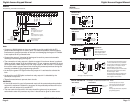
DOOR SENSING
Required for:
• Door Auto Relock
• Door Forced-open Alarm
• Door Propped-up Alarm
• Mantrap (Interlock) Control
The Key Active Output will switch to ground (-
) for 10 seconds whenever a key is touched.
Use to turn ON an LED and/or a small buzzer
to notify a guard, or to energize a relay to
switch ON lights or CCTV camera.
Only one connection option is recommended.
Make sure the current does not exceed the
maximum rating of 100mA.
An external power supply and isolation relay
are necessary to drive high power devices
such as lights or CCTV cameras.
(8)
(9)
(10)
(11)
(12)
RELAY OUTPUT #2
--
Example, to shunt an alarm N.C. zone
WIRE HARNESS WIRE HARNESS
Wire
Harness
Use Normally Open (N.O.) output
contact to shunt a Normally Closed
(N.C.) protection zone of an alarm
system.
Set relay output #2 to Start / Stop mode
(programming option 51)
WHITE/BROWN
BLUE
N.C.
N.C. magnetic contact
To protection zone of an
alarm control panel
OR
WIRING:
Auxiliary Accessories
(See page 15 for jumper selection)
Page 6 Page 11