


SECO-LARM U.S.A., Inc.
E-941SA-80 Installation Manual
E-941SA-80
Installation Manual
Page 2 Page 3
A. Drill holes for the mounting plate and
armature plate (see fig. 1 and 2) by
doing the following:
1. Fold the mounting template along
the dotted line
2. Close the door. Find a mounting
location on the door frame near the
upper free-moving corner of the
door, as close to the corner of the
door frame as possible.
3. Place the template against the door
and frame.
4. Drill two holes in the door frame for
the mounting plate and three holes
in the door as indicated on
template.
5. Only from the sexnut bolt side of the
door, enlarge the 5mm hole to
9mm.
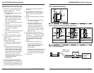
B. Mount the armature plate to the door
using the two steel and one rubber
washer (fig. 2):
NOTE — Actual installation varies
according to door style.
1. Secure the two guidepins into the
two side holes of the armature
plate.
2. Insert the armature screw into the
armature plate, then put the rubber
washer between two steel washers,
and place them over the armature
screw between the armature plate
and the door. This will allow the
armature plate to pivot slightly
around the armature screw in order
to compensate for door
misalignment.
2. Insert the sexnut bolt into the 9mm
hole, then tighten the sexnut bolt and
the armature screw, just enough so the
armature plate can withstand the force
of someone attempting to break down
MOUNTING THE E-941SA-80Q
the door while the electromagnet is
engaged.
3. Do not tighten the armature plate
against the door. The plate must be
able to pivot around the armature
screw.
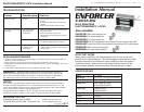
C. Screw the mounting plate to the door
frame:
1. Remove the L-shaped mounting
plate from the magnet.
2. Insert the provided two
1
/
8
" x 1"
(4 x 25.4 mm) screws into the
L-shaped mounting plate and
screw it to the door frame. The
armature plate and the mounting
plate must be concentric or align
with each other.
D. Drill the power cable access hole.
E. Mount the electromagnet to the door
frame (fig. 1) — Use the Allen wrench
to screw the socket-head mounting
screws through the bottom of the
electromagnet into the mounting
bracket.
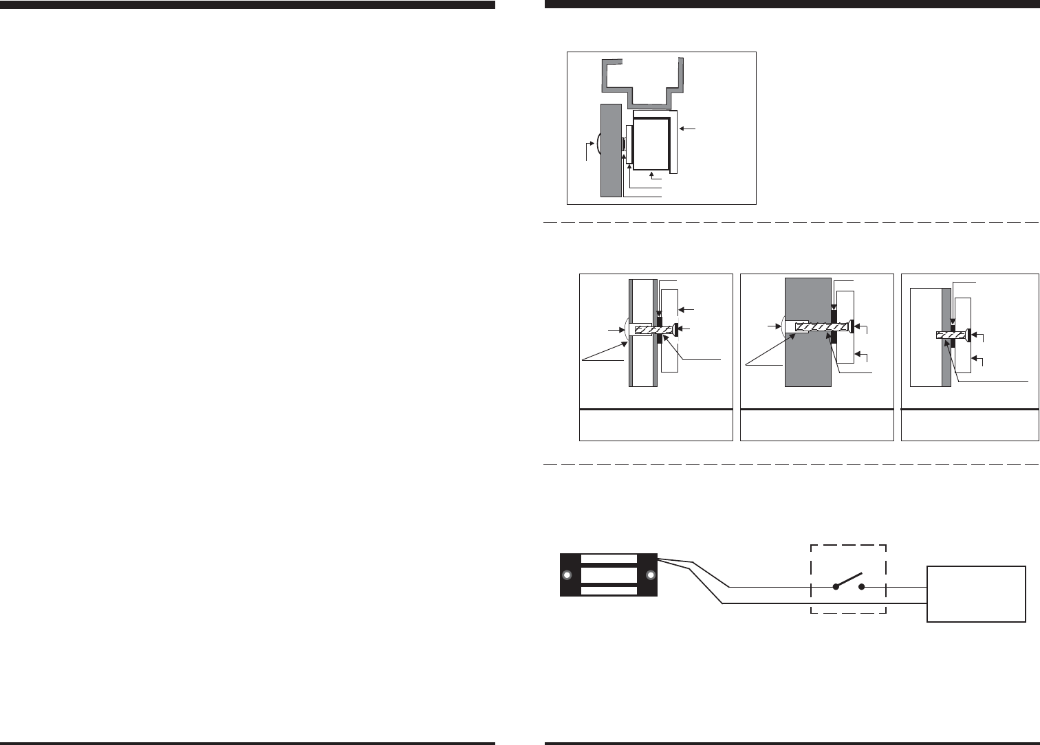
F. Connect the power leads (fig. 3):
1. Run two power leads from the
power supply through the power
cable access hole into the
electromagnet.
2. Connect the power leads to the red
and black power input wires of the
unit. Observe correct polarity, red
for positive and black for negative.
G. Test the unit.
Sexnut
bolt
This side drill
9mm only
Drill a 5mm
hole thru door
Armature
Screw
Steel and
Rubber
washers
(as
needed)
Armature
HOLLOW METAL DOOR
Drill an 5mm hole thru door. From sexnut
bolt side only, enlarge the 5mm hole to
9mm.
Drill an 5mm hole thru door. From sexnut
bolt side of door, drill 9mm (
23/64
") hole,
25mm in depth.
Drill a 3.5mm dia. hole and tap for
M5 x 0.8 thread.
Sexnut
bolt
Drill 9mm
(23/64")
Drill a 5mm
hole thru door
Armature
Screw
Armature
SOLID CORE DOOR
Armature Screw
Tap M5 x 0.8 Thread
REINFORCED DOOR
Armature
FIG.1 Standard Mounting
FIG. 2 Types of armature plate mounting
FIG. 3 Wiring diagram
Steel and
Rubber washers
(as needed)
Steel and
Rubber washers
(as needed)
Power wires to
electromagnet
Control
Device
+
-
Red
Black
12~24VDC
Power
Supply
L-shaped
Maounting
bracket
Magnet
Sexnut
bolt
Armature Plate
Steel and Rubber washers