


SECO-LARM ELECTROMAGNETIC LOCK
6 SECO-LARM U.S.A., Inc.
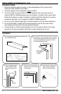
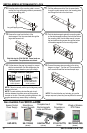
14. Cut the wires so they are long enough to connect
with the terminal block. Set the voltage using the
selection jumpers based on your input voltage.
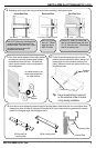
10. Once the position of the mounting plate is correct,
use the four long self-tapping screws to permanently
mount the mounting plate.
11. Drill the cable access hole. Run the power leads
through the cable access hole in the mounting plate
and through the hole in the door frame.
12. Remove the cover from the front of the
electromagnet. Run the power leads through the
large cable access hole .
13. Push the electromagnet against the mounting plate
so the electromagnet ends are flush with the ends of
the mounting plate. Use the Allen wrench to screw
the hex-head mounting screws through the bottom
of the electromagnet into the mounting bracket.
EAP-5D1Q
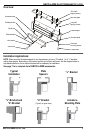
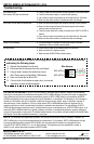
Also Available from SECO-LARM:
SK-1123-SQ
SD-7202GC-PEQ
Long self-tapping screws
Position a jumper over
the two middle pins for
24VDC operation
Position two jumpers
on all four pins for
12VDC operation
Voltage Selection Jumpers
Access Control
Power Supply
Stand-Alone
Access Keypads
Wired or Wireless
RTE Plates
(shown)
Voltage
Converters or
Booster
ST-LA110-TTQ
(shown)
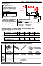
NOTE: This should be the very last step, as once the
tamper caps are in place they are very difficult to remove.
NOTE: Failure to correctly set the input voltage may cause
damage to the lock.
NOTE: Connect switching devices like push-to-exit
switches between the power source and the positive
terminal on the lock. Connecting switching devices to the
negative terminal may cause a delay in unlocking.
Complete line of
Electromagnetic
Locks and Strikes
E-941DA-1K2P
(shown)
(shown)
15. Connect the power wires according to the wiring
diagram on page 7. Test the unit. Then replace the
front cover and install the hex-head tamper caps.
Skip this step for E-941SA-300. Power leads are
pre-installed. Faceplate does not detach.