10. Sequence of Operation & Diagnostics
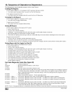
The following is the normal operating sequence for the control system.
Cooling (¥) Request:
24 VAC signals applied to Y & G terminals of EFT (electronic fan timer) control.
• Cool motor speed energized after 6 second Cool Fan On Delay time.
Y & G signals removed from EFT.
• Cool motor speed de-energized after 60 second Cool Fan Off Delay time.
Circulating Fan (G) Request:
24 VAC signals applied to G terminals of EFT control.
• Heat motor speed energized without delay.
G signal removed from EFT.
• Heat motor speed de-energized without delay.
Heating (W) Request:
24 VAC signals applied to W terminal of EFT control.
• Inducer motor turns on.
• The gas valve solenoid energizes.
• Following a 3 second prepurge delay, the pilot valve opens and the ignitor begins to warm up.
• After the pilot lights, the main burners energize and light.
• Timed from the opening of the main gas valve, the control will delay 30 seconds before switching the fan to Heat speed.
W signal removed from EFT.
• The gas valve de-energizes and the main burners go out.
• The inducer runs at its present speed for a 30 second postpurge period.
• Timed from the gas valve de-energizing, the Heat fan speed de-energizes after the selected Heat Fan Delay time expires.
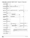
Heating Request with Gas Supply Line Shut Off:
24 VAC signals applied to W terminal of EFT control.
• Inducer motor turns on.
• The gas valve solenoid energizes.
• Following a 3 second prepurge delay, the pilot valve opens and the ignitor begins to warm up.
• The ignitor glows red-hot for 30 seconds, then turns off.
• The igniter stays off for 25 seconds, then begins to warm-up again.
• The igniter glows red-hot for 30 seconds, then turns off.
• The pilot valve closes 3 seconds after the igniter de-energizes.
• The inducer de-energizes 5 seconds after the pilot valve closes.
• The SmartValve proceeds to soft lockout and flashes error code 6.
• The control exits soft lockout after 5 minutes and begins
another ignition sequence.
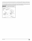
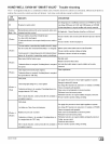
Gas Valve Diagnostic Codes (See Figure 43)
OFF = Control not powered
Heartbeat = Normal Operation (Standby or call for heat)
1 Flash = Not used
2 Flashes = Pressure switch closed when should be open
3 Flashes = Pressure switch circuit was still sensed as open 30 seconds after the inducer was energized. System is
in 5 minute delay mode, with inducer off. After 5-minute delay, a new ignition sequence will be initiated.
(Note: SV9541M On/Off switch in off position during a call for heat will generate this diagnostic code)
4 Flashes = Limit switch string open
5 Flashes = Flame sensed out of sequence - Flame signal still present.
6 Flashes + 1 Note 1 = Soft Lockout -Maximum retry count exceeded (failed to light within 4 trials for ignition)
6 Flashes + 2 Notes 1,2 = Soft Lockout -Maximum recycle count exceeded - Last failure was Flame Sense Lost During Run
6 Flashes + 3 Notes 1,2 = Soft Lockout -Maximum recycle count exceeded - Last failure was Airflow Proving Circuit Opened
During Run
6 Flashes + 4 Notes 1,2 = Soft Lockout -Maximum recycle count exceeded - Last failure was Limit Circuit Opened During Run
7 Flashes = Soft Lockout Due to Limit Trips Taking Longer than 2 minutes to Reset; Auto Reset After 1 Hour if
Call for Heat Still Present. Reset by Cycling Call for Heat at Any Time.
NOTE 1: The 6 + X designation indicates a combination of flash codes: 6 flashes shows the control is in soft lockout, followed by X flashes
[_ 44001 111400


