10. Sequence of Operation & Diagnostics
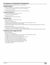
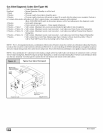
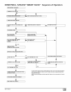
The following is the normal operating sequence for the control system.
Cooling (¥) Request:
24 VAC signals applied to Y & G terminals of EFT (electronic fan timer) control.
• Cool motor speed energized after 5 second Cool Fan On Delay time.
Y & G signals removed from EFT.
• Cool motor speed de-energized after 90 second Cool Fan Off Delay time.
Circulating Fan (G) Request:
24 VAC signals applied to G terminals of EFT control.
• Heat motor speed energized without delay.
G signal removed from EFT.
• Heat motor speed de-energized without delay.
Heating (W) Request:
24 VAC signals applied to W terminal of EFT control.
• Inducer motor turns on.
• The gas valve solenoid energizes.
• Following a 3 second prepurge delay, the pilot valve opens and the ignitor begins to warm up.
• After the pilot lights, the main burners energize and light.
• Timed from the opening of the main gas valve, the control will delay 30 seconds before switching the fan to Heat speed.
W signal removed from EFT.
• The gas valve de-energizes and the main burners go out.
• The inducer runs at its present speed for a 30 second postpurge period.
• Timed from the gas valve de-energizing, the Heat fan speed de-energizes after the selected Heat Fan Delay time expires.
Heating Request with Gas Supply Line Shut Off:
24 VAC signals applied to W terminal of EFT control.
• Inducer motor turns on.
• The gas valve solenoid energizes.
• Following a 3 second prepurge delay, the pilot valve opens and the ignitor begins to warm up.
• The ignitor glows red-hot for 30 seconds, then turns off.
• The igniter stays off for 25 seconds, then begins to warm-up again.
• The igniter glows red-hot for 30 seconds, then turns off.
• The pilot valve closes 3 seconds after the igniter de-energizes.
• The inducer de-energizes 5 seconds after the pilot valve closes.
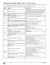
• The SmartValve proceeds to soft lockout and flashes error code 6.
• The control exits soft lockout after 5 minutes and begins
another ignition sequence.
44001 102004 [_


