


STEPS TO INSTALL YOUR WATER HEATER (Continued)
WARNING
I,i [__PJ
If the temperature and pressure relief valve ever needs replacing,
use onty a valve specified by local codes, but not less than a
combination temperature and pressure relief valve certified by a
nationally recognized testing laboratory that maintains periodic
inspection of production of listed equipment or materials meeting
the requirements for Relief Valves and Automatic Gas Shutoff
Devices for Hot Water Supply Systems, as specified in the latest
edition of ANSI Z21.22. This valve must be marked with a
maximum set pressure not to exceed the marked maximum
working pressure of the water heater. (The relief valve provided
with this heater meets these.requirements.) Install the
replacement valve into the opening provided and marked for this
purpose on the water heater. Do not place any valve between the
temperature and pressure relief valve and the tank. Orient it or
provide tubing so that any discharge from the valve witll exit only
within 6 in. above (or any distance) below the structural floor and
cannot contact any live electrical part. The discharge opening
must not be blocked or reduced in size under any circumstances.
For maintenance and replacement of the temperature and
pressure relief valve see pages 10 and 11.
IMPORTANT; TO HELP PREVENT POSSIBLE DAMAGE TO
THE WATER HEATER, WE SUGGEST YOU READ STEP 5
CAREFULLY.
DRAIN PIPE FROM TEMPERATURE AND
• PRESSURE RELIEF VALVE.
WARNING
The temperature and pressure relief valve is designed to
automatically open to vent dangerously high temperature or
pressure from the water heater. To vent the temperature or
pressure,thedrain pipe mustallow afree flow of water to a floor drain
or other suitable drain point (CHECK LOCAL CODES). If it cannot
vent properly,and fast enough, the heater could burst and damage
property,or causeseverepersonal injury. BE SURETO FOLLOWALL
GUIDES BELOWWHEN INSTALLINGTHIS DRAIN PIPE.(Alsoread
the safetyguideson page2, and"WARNING" above.)
DO NOToperate the water heater unless the temperature and pres-
sure relief valve is in place, correctly piped and working properly.
CAUTION: Do not apply heat to the fitting when making sweat
connections to the temperature and pressure relief valve.Sweat
an adaptorto the copper line before connecting to the valve.It is
imperativethat no heat be applied to the water heater connec-
tions asthey arejoinedto the non-metalic structureof the heater.
• If the temperature and pressure relief valve needs
repositioning, removing or replacing, two wrenches must
be used -- one to turn the valve and one to hold the union
hex nut. Never use only one wrench.
= Use 3/4" pipe and fittings the same size as the outlet of the
temperature and pressure relief valve. DO NOT USE A
SMALLER SIZE PIPE.
• Use material that will withstand hot water (210°F), and will
not distort, deform, melt, collapse, etc. Copper or CPVC
plastic pipe and fittings are best to use, to keep weight
stress on the center hex union at a minimum.
• DO NOT install valves or fittings in the drain pipe that will
restrict drain flow.
• The end of the drain pipe must not have threads, so a
fitting or cap could be turned onto it by mistake.
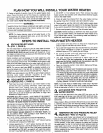
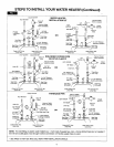
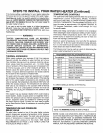
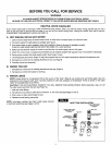
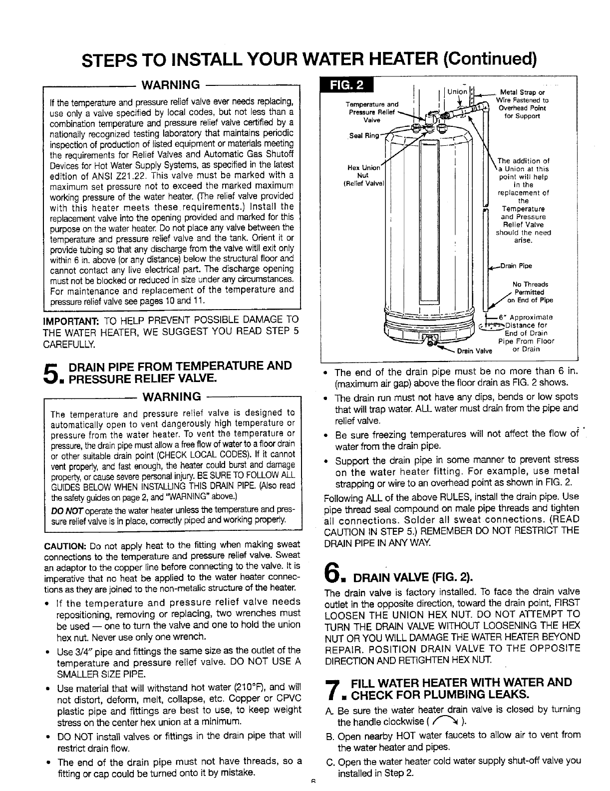
Temperature and
Pressure
Valve
•Seal Ring
Hex Union _'
Nut
(Relief Valve
-e----. Metal Strap or
_. Wire Fastened to
Overhead Point
_ for Support
I I\ The addition of
I I \a Union at this
II pointwillhelp
[ I in the
I I replacement of
[_ the
tri Temperature
II and Pressure
I] Relief Valve
II should the need
i; arise.
Drain Pipe
I I No Threads
I I ./ Permitted
IL_ on End of Pipe
I !_r
_-6" Approximate
---- _ ,__/_-"_"_DIs tan for
....._--- _ _ _ ce
_--....L_-r-DqlIi_lt---T_ End of Drain
_ _-._ Pipe From Floor
Drain Valve or Drain
• The end of the drain pipe must be no more than 6 in,
(maximum air gap) above the floor drain as FIG. 2 shows.
• The drain run must not have any dips, bends or low spots
that will trap water. ALL water must drain from the pipe and
relief valve.
• Be sure freezing temperatures will not affect the flow of '
water from the drain pipe.
• Support the drain pipe in some manner to prevent stress
on the water heater fitting. For example, use metal
strapping or wire to an overhead point as shown in FIG.2.
Following ALL of the above RULES, install the drain pipe. Use
pipe thread seal compound on male pipe threads and tighten
all connections. Solder all sweat connections. (READ
CAUTION IN STEP 5,) REMEMBER DO NOT RESTRICTTHE
DRAIN PIPE INANY WAY.
,, DRAIN VALVE (FIG. 2).
The drain valve is factory installed. To face the drain valve
outlet in the opposite direction, toward the drain point, FIRST
LOOSEN THE UNION HEX NUT. DO NOT ATTEMPT TO
TURN THE DRAIN VALVE WITHOUT LOOSENING THE HEX
NUT OR YOU WILL DAMAGE THE WATERHEATERBEYOND
REPAIR. POSITION DRAIN VALVE TO THE OPPOSITE
DIRECTIONAND RETIGHTENHEXNUT.
FILL WATER HEATER WITH WATER AND
• CHECK FOR PLUMBING LEAKS.
A. Be sure the water heater drain valve is closed by turning
the handle clockwise ( _ ).
B. Open nearby HOT water faucets to allow air to vent from
the water heater and pipes.
C. Open the water heater cold water supply shut-off valve you
installed in Step 2.