


INSTALLATION / OPERATION / ELECTRICAL
PUMP INSTALLATION
Set the pump on the bottom of the sump, making sure that
it sits solidly and is level. Be sure there is enough space
around the punlp to allow the switch frec mo_ cnlcnt ;is the
stimp water level changes. Du Rot iitstall the ptimp on clay,
earth, or sand surlTace.
i
I_" CAUTION IRisk
. I of flooding. If a flexible discharge
hose is used, pump may move around in sump when
niotor starts. If it moves far enough so that tile switch hits
the side of the sump, the switch may stick and prevent
pump from starting. Make sure that pump is secured so that
it cannot walk arotmd in sump.
Hose Kit No. 27909 can be used as the discharge pipe. Run
the discharge pipe to the nearest sewer outlet or other point
of disposal. Use the most direct route and the fewest turns
and elbows possible.
Use Teflon tape to seal threads in plastic pipe. Hand tighten
only.
NOTE: To avoid backflow into sump when pump shuts off,
install a Check Valve, SEARS Stock No. 2789, in threaded dis-
charge port of pump. A SEARS No. 2789 Check Valve is con-
structed with an anti-aiflock hole. Ifyou use a SEARS No. 2792
or any other check valve, drill a 1/8" hole in the discharge pipe
just above the pump discharge port and below the Check
Valve to prevent pump from airlocking.
Make sure the air-bleed hole is down inside the sump so that
it does not run water on the basement floor when the pump
is mnning.
AUTOMATIC FLOAT SWITCH
INSTALLATION AND OPERATION
Your SEARS Model 390.305001 Submersible Drainer comes
with the automatic float switch mounted on the motor hous-
ing ready for operation. Tether length is factory set at 3"
(76mm). Do not change tether length. See Page 6 for verti-
cal float switch instructions.
IAWARNING_ Risk of electric shock. Always disconnect
the pump and switch from the electrical power source
before doing any maintenance!
Follow instructions below to install pump with factory
mounted switch:
1. Be sure automatic float can swing freely through its entire
arc without interference from pump, piping, sump wall
or any other object.
2. Plug the automatic switch cord into a properly grounded
outlet (see "Electrical Connections", Page 4). Plug the
pump power cord into the back of the switch plug.
3. Test the installation by adding water to the sump pit until
pump operates normally as follows:
A.When sump is dry, the watertight automatic float
switch is hanging in a downward position and the
pump is off.
B. As water comes into the sump, tile auton/atic float
switch rises to an upward position and the pump starts.
(7.Water will contint_e to be pumped until the float switch
is hanging ill the dox_nward position agaiit, when
pump will stop.
DO NOT ALLOW PUMP TO RUN DRY!
Be sure to leave at least 5" (127mm) of water above
pump base plate when pump stops. Running pump
dry could ruin the pump and will void the warranty.
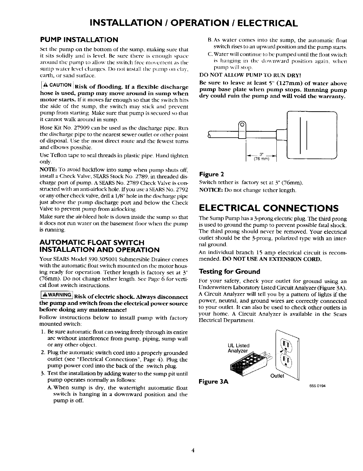
Figure 2
Switch tether is factor), set at 3" (76mm).
NOTICE: Do not change tether length.
ELECTRICAL CONNECTIONS
The Sump Pump has a 3-prong electric plug. The third prong
is used to ground the pump to prevent possible fatal shock.
The third prong should never be removed. Your electrical
outlet should be the 3-prong, polarized type with an inter-
nal ground.
An individual branch 15 amp electrical circuit is recom-
mended. DO NOT USE AN EXTENSION CORD.
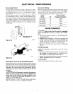
Testing for Ground
For your safety, check your outlet for ground using an
Underwriters Laboratory Listed Circuit Analyzer (Figure 3A).
A Circuit Analyzer will tell you by a pattern of lights if the
power, neutral, and ground wires are correctly connected
to your outlet. It can also be used to check other outlets in
your home. A Circuit Analyzer is available in the Sears
Electrical Department.
UL Listed [_
Figure 3A
665 0194
4