


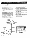

Installation Checklist
BEFORE LIGHTING THE PILOT:
1. Check the gas lines for leaks.
a. Use a soapy water solution. DO NOT test for
gas leaks using a match or open flame.
b. Brush the soapy water solution on all gas pipes,
joints and fittings.
c. Check for bubbling soap. This means you have
a leak. Turn "OFF" gas and make the necessary
repairs.
d. Recheck for leaks.
e. Rinse off soapy solution and wipe dry.
2. Is the new temperature-pressure relief valve prop-
erly installed and piped to an adequate drain? See
"Temperature-Pressure Relief Valve" section.
3. Are the cold and hot water lines connected to the
water heater correctly? See"Water Piping" instruc-
tions in the "Installing the New Water Heater" sec-
tion.
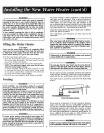
4. Is the water heater completely filled with water?
See "Filling the "Water Heater" instructions in the
"installingthe New Water Heater" section.
5. Will a water leak damage anything? See the
"Locating the New Water Heater" section.
6. Is there proper clearance between the water heater
and anything that might catch fire? See the
"Locating the New Water Heater" section.
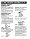
7. Do you have adequate ventilation so that the
water heater will operate properly? See
"Combustion Air and Ventilation" in the "Locating
the New Water Heater" section.
8. Is the draft hood vent piping properly secured? See
"Venting" instructions in the "Installing the New
Water Heater" section.
9. Is there proper clearance between the vent pipe
and anything that might catch on fire? See
"Venting" instructions in the "Installing the New
Water Heater" section.
10. Is the vent pipe properly sloped and does the vent
terminate outdoors? See "Venting" instructions in
the "Installing the New Water Heater" section.
11. Do you need to call your gas company to check
the gas pipe and its hookup?
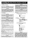
VENT PIPETO
OUTDOORS
OR CHIMNEY
GAS SUPPLY
SHUTOFF VALVE
TEE
DRIP
(SEDIMENT TRAP)
i-
PIPE CAP
DRAFTHOOD
UNION
COLD
SHUTOFF VALVE
TEMPERATURE-PRESSURE
RELIEF VALVE
/
DISCHARGE LINE
(Do not cap or plug)
DRAIN VALVE
6 INCH AIR GAP
MODEL RATING PLATE
FLOOR DRAIN
Figure 11 1
13