14
IMPORTANT: The water heater should be located in an area where
leakage of the tank or connections will not result in damage to the
area adjacent to the water heater or to lower floors of the structure.
Due to the normal corrosive action of water, the tank will eventually
leak after an extended period of time. Also any external plumbing
leak, including those from improper installation, may cause early
failure of the tank due to corrosion if not repaired. If the homeowner
is uncomfortable with making the repair a qualified technician should
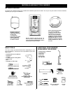
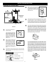
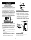
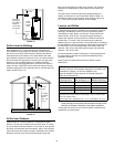
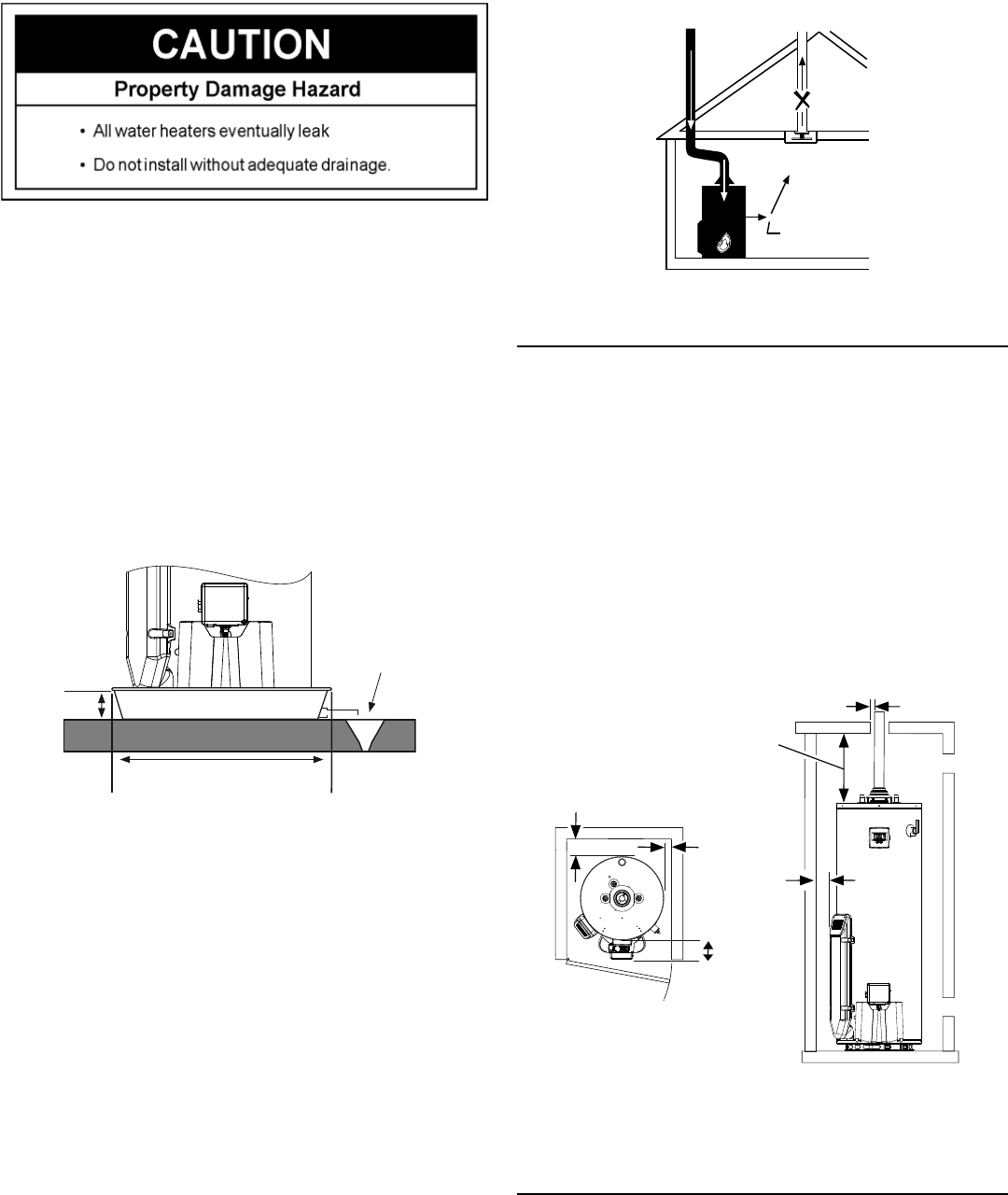
be contacted. A suitable metal drain pan should be installed under
the water heater as shown below, to help protect the property from
damage which may occur from condensate formation or leaks in
the piping connections or tank. The pan must limit the water level
to a maximum depth of 1-3/4” and be two inches wider than the
heater and piped to an adequate drain. Locate the water heater
near a suitable indoor drain. Outside drains are subject to freezing
temperatures which can obstruct the drain line. The piping should be
at least 3/4” ID and pitched for proper drainage.
1-3/4”
max.
At least 2” greater
than the water heater.
Pipe to an
adequate drain
Water heater life depends upon water quality, water usage, water
temperature and the environment in which the water heater is
installed. Water heaters are sometimes installed in locations
where leakage may result in property damage, even with the use
of a metal drain pan piped to a drain. However, unanticipated
damage can be reduced or prevented by a leak detector or water
shut-off device used in conjunction with a piped metal drain
pan. These devices are available from some plumbing supply
wholesalers and retailers, and detect and react to leakage in
various ways:
• Sensors mounted in the metal drain pan that trigger an alarm
or turn off the incoming water to the water heater when water
is detected.
• Sensors mounted in the metal drain pan that turn off the
water supply to the entire home when water is detected in
the metal drain pan.
• Water supply shut-off devices that activate based on the
water pressure differential between the cold water and hot
water pipes connected to the water heater.
• Devices that will turn off the gas supply to a gas water heater
while at the same time shutting off its water supply.
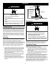
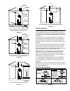
REVERSE FLOW
OF GASES
EXHAUST FAN
FIGURE 10.
Clearances and Accessibility
NOTE: Minimum clearances from combustible materials are
stated on the label on the front of the heater adjacent to the gas
control valve/thermostat of the water heater.
The water heater is certified for installation on a combustible
floor.
• IMPORTANT: If installing over carpeting, the carpeting must
be protected by a metal or wood panel beneath the water
heater. The protective panel must extend beyond the full
width and depth of the water heater by at least five inches
(127mm) in any direction; or if in an alcove or closet installa-
tion, the entire floor must be covered by the panel.
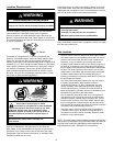
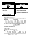
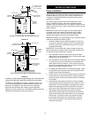
• Figure 11 may be used as a reference guide to locate the
specific clearance locations. A minimum of 5 inches of front
clearance should be provided for inspection and service.
Ceiling
Top View
Minimum Clearance Locations
0” min.
Back
0” min.
Sides
5” min.
Front
12” min.
Top to
6” min. at
Single Wall
Vent Pipe
0” min.
Air Inlet
Chamber
FIGURE 11.
High Altitude Installation
This water heater should not be installed for operation at
elevations above 10,100 ft. (3,078 m).
FIGURE 9.


