


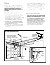
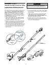
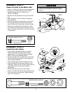
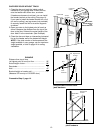
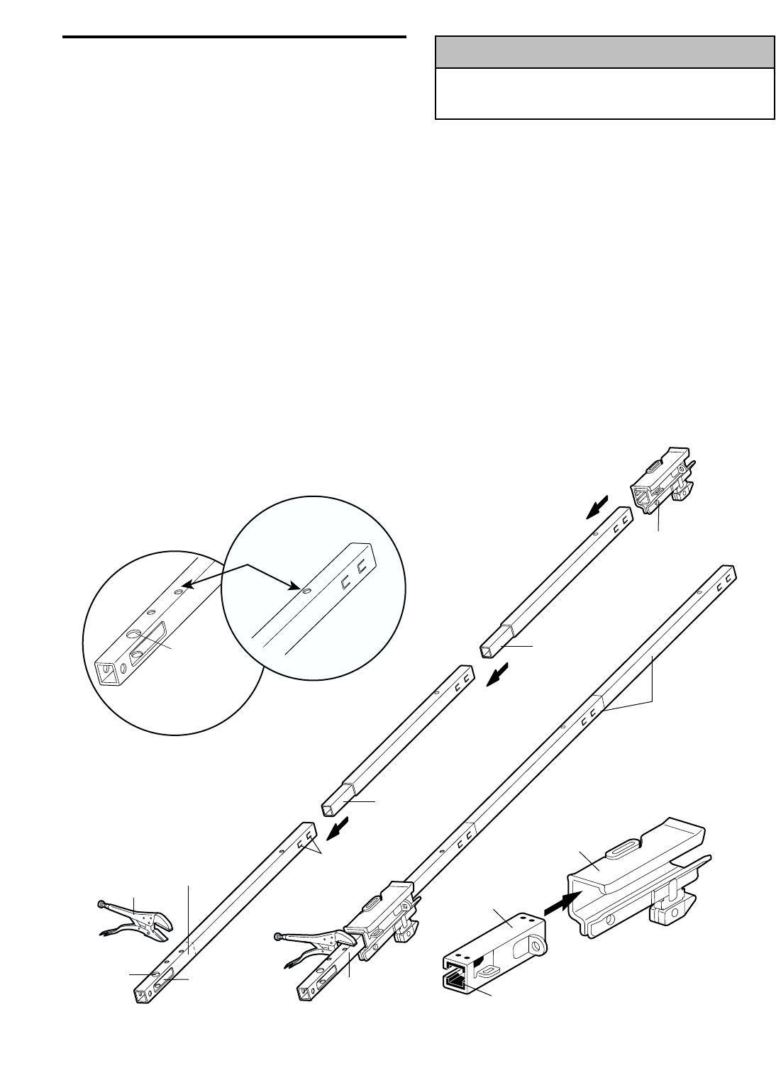
The front rail has a cut out “window” at the door end
(see illustration). The hole above this window is
larger on the top of the rail than on the bottom. A
smaller hole 3-1/2" away is close to the rail edge.
Rotate the back rail so it has a similar hole close to
the opposite edge, about 4-3/4" from the far end. A
3-piece rail uses two back rails.
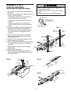
1. Remove the straight door arm, hanging brackets
and clevis pin packaged inside the front rail and
set aside for Installation Step 5 and 12.
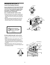
2. Align the rail sections on a flat surface exactly as
shown and slide the tapered ends into the larger
ones. Tabs along the side will lock into place.
3. Place the motor unit on packing material to protect
the cover, and rest the back end of the rail on top.
For convenience, put a support under the front
end of the rail.
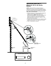
4. As a temporary trolley stop, clamp a locking pliers
onto the rail, 8" from the center of the idler pulley
hole, as shown.
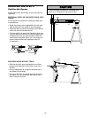
5. Check to be sure there are 4 plastic wear pads
inside the inner trolley. If they became loose
during shipping, check all packing material. Snap
them back into position as shown.
6. Connect the inner and outer trolleys as shown.
7. Slide the trolley assembly along the rail from the
back end to the locked pliers.
8
Front Rail
(TO DOOR)
Window
Cut-Out
Locking Pliers
Idler
Pulley
Hole
8" Distance from
Idler Pulley Hole
Tabs
Back Rails
(TO MOTOR UNIT)
Trolley
Tapered
End
Tapered
End
Inner Trolley
Wear Pads
Outer Trolley
KEEP LARGER
HOLE ON TOP
FRONT RAIL
(TOP)
KEEP SMALL HOLES
ALONG OPPOSITE EDGE
OF RAILS
BACK RAIL
(TOP)
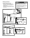
To prevent INJURY from pinching, keep hands and
fingers away from the joints while assembling the rail.
WARNING
CAUTION
WARNING
WARNING
ASSEMBLY STEP 1
Assemble the Rail & Install the Trolley
To avoid installation difficulties, do not run the
garage door opener until instructed to do so.