


26 Medalist Pro Installation Guide, Rev. B
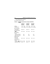
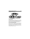
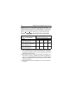
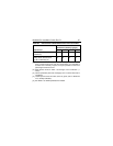
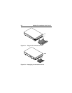
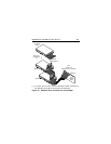
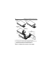
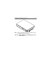
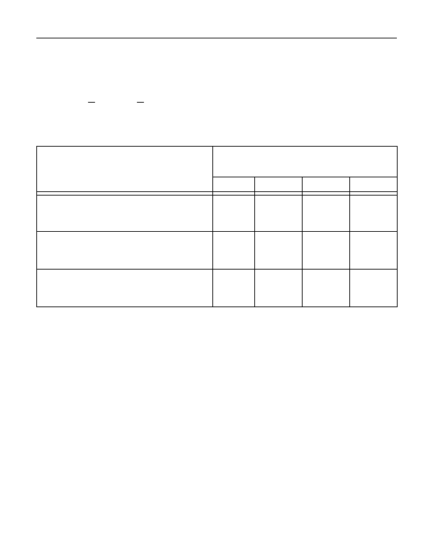
Figures 3a, 3b, 3c, and 3d show typical drive connections. The
following table lists the maximum cable lengths and number of
devices with single-ended I/O circuits allowed on a daisy-chain
cable for <
10 and <20 M transfers/sec I/O data transfer rates.
[1] For environments where all elements of the bus (cables, device inter-
faces, environmental noise and other parameters) are controlled to
be better than minimally required, it may be possible to extend the
path length and device count.
[2] Extending the device count beyond eight requires specification con-
trol beyond the minimum specified in the ANSI T10/1302D docu-
ment. It is recommended that the devices be uniformly spaced
between terminators with the end devices located as close as possi-
ble to the terminators.
[3] Values specified by data rate shall apply even if a slower data rate is
negotiated.
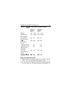
Table 4a. Interconnect characteristics for single-ended
I/O circuits
Number of attached SCSI
devices
Maximum distance between
terminators (meters) [1] [3]
Fast-5 Fast-10 Fast-20 Fast-40
1 to 4 maximum capacitance
(25pF) SCSI devices
63 3 N/A
5 to 8 maximum capacitance
(25pF) SCSI devices
63 1.5N/A
9 to 16 maximum capacitance
(25pF) SCSI devices
6 3 [2] N/A