1
2
3
4
5
6
V-4
SM831148
5. Outdoor unit maintenance remote control
Display (functions)
• Use the temperature setting
and buttons to change the item code.
skrameRstnetnoc yalpsiDedoc metI
00 (1)
sutats laitini tAlamron nehw FFO :)edoc( stnetnoc mrala tinu roodtuO
Blinking 8-alarm code display at pre-trip, LED (2)
01 No. of indoor units connected in that refrigerant system
02 Unit. Nos. of connected indoor units in that refrigerant system *2
03 Operating status of indoor units in that refrigerant system (blinks when alarms occur) *2
04 Unit Nos. of indoor units in that refrigerant system where the thermostats are ON *2
05 No. of outdoor units connected in that refrigerant system
No. of connected
units: 1
06 Unit Nos. of connected outdoor units in that refrigerant system *2
07 Operating status of outdoor units in that refrigerant system (blinks when alarms occur) *2
08
09
0A
0b
0C
0d
0E
0F
10 Total compressor operating time (in 1-hr. units) *3
11
12
13
14
15
16 Total power ON time of outdoor unit (in 1-hr. units)
17 Compressor start count
18
19
FE Outdoor unit microcomputer firmware version
FF Outdoor unit microcomputer software version
* See following page for *2 and *3.
(3) XX-YY R.C.
Displays the outdoor unit address of the selected outdoor sub-bus.
XX = Main bus line outdoor system address (1 – 30)
YY = Outdoor unit address in outdoor sub-bus (1 – 4). This is “1” when
there is only 1 outdoor unit.
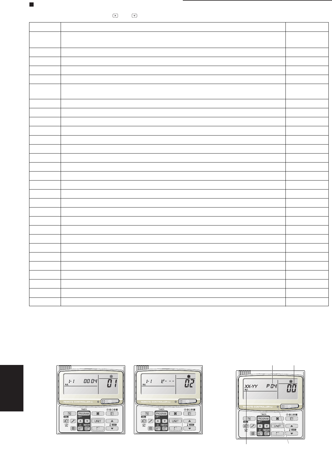
02: <Unit Nos. 1, 2, 3, and 4 are connected>
<Sample displays>
01: <No. of connected indoor units>
4 units connected
Locations where (1), (2), and (3) are displayed
are shown below.
LED
(3)
(1)
(2)


