2
Assembling the Outdoor Housing
● For the built-in heater and fan in the dome cover, you need an additional 24 V AC power supply.
● This housing is used in combination with a dome cover (clear/smoked) and a mounting bracket (wall/
pendant) that are sold separately.
☞ For how to install an assembled housing, refer to the instruction manual for the bracket used.
Also refer to the instruction manual for each associated device.
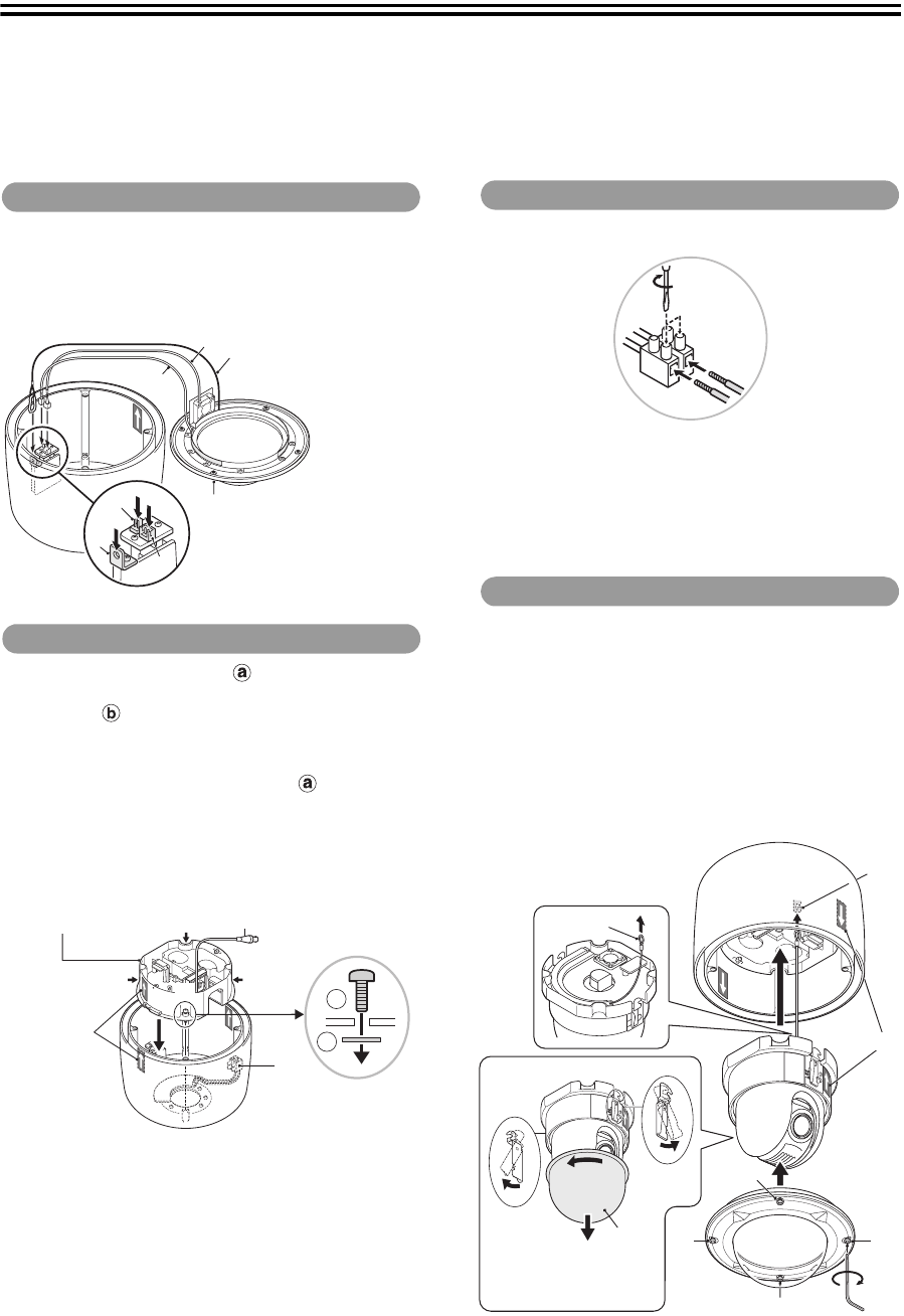
1
Hook the safety wire (A) of the dome cover on hook
hole (A’) located inside the housing.
2
Connect the heater cable (B) to the heater terminal
(B’) and the fan cable (C) to the fan terminal (C’).
1
Pass the supplied screws through power board
unit screw holes (D) and fasten them loosely using
washers (4 places).
2
Mount the power board unit in the housing aligning
the arrows (E) of the same color (blue) on them,
and then firmly tighten the screws loosely
fastened in the previous step.
• Make sure the terminal (F) and its cable are located
along the inner lateral face of the housing.
• Pull the video cable led from the ceiling or wall
toward the power board unit.
3
Fix the housing onto the mounting bracket (wall/
pendant).
☞ For details, please refer to “Outdoor Type” in the
Mounting Bracket Instruction Manual.
1
Connect the 24 V AC power cable to the terminal (F).
2
Connect other cables to the power board unit.
☞ For details, please refer to “Connections and Settings”
in the Installation Manual that comes with the camera
unit.
1
Fasten the camera unit safety wire (G) to the hook
(G’) inside the power board unit.
2
Align the arrows (E) of the same color (blue) on the
camera unit and the housing inner face, and push
the camera until you hear a click.
3
Remove the plastic cover (H) of the camera unit.
4
Attach the dome cover by fastening 4 screws (J)
using the supplied hexagonal wrench.
1. Attaching the dome cover
A
B
C
A’
B’
C’
Dome Cover:
• VA-CM8C (Clear)
• VA-CM8S (Smoked)
2. Mounting the power board unit
D
D
D
D
a
b
F
E; Blue
Video cable
Power Board Unit:
VA-84S/80S
3. Connecting cables
F
4. Mounting the camera unit
G
H
J
J
J
J
G’
*
*
E; Blue
*To remove the camera unit
L9BHK_WA(VA-80EX).book 2 ページ 2007年1月12日 金曜日 午後3時35分


