


SM830043
– 68 –
4
4. Service procedures
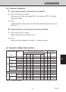
4-4 Checking the Electrical Components
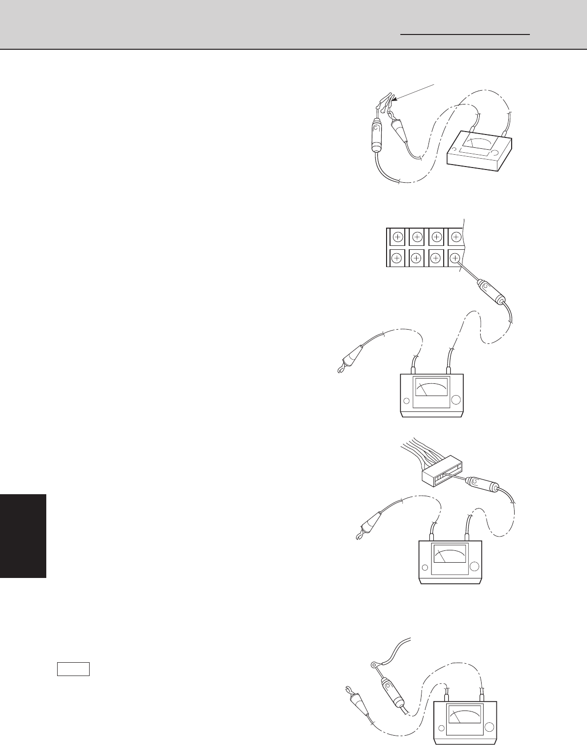
(1) Measurement of Insulation
Resistance
• The electrical insulation is acceptable when the
resistance exceeds 1 MΩ.
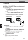
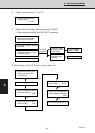
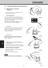
1 Power Supply Wires
Clamp the earthed wire of the Power Supply wires
with a lead clip of the insulation resistance tester and
measure the resistance by placing a probe on either
of the power wires. (Fig. 42)
Then measure the resistance between the earthed
wire and the other power wires. (Fig. 42)
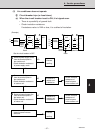
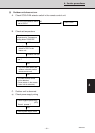
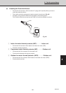
2 Indoor Unit
Clamp an aluminum plate fin or copper tube with the
lead clip of the insulation resistance tester and
measure the resistance by placing a probe on the
terminal plate (Fig. 43)
3 Outdoor Unit
Measure the resistance by placing a probe on the
terminal plate in the same manner as explained
above 2. (Fig. 43)
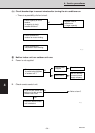
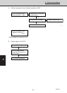
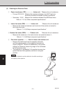
4 Measurement of Insulation Resistance for
Electrical parts
• Disconnect the connector of the desired electric
part from terminal plate, P.C.B. Ass’y, etc. (Fig. 44)
• Similarly, disconnect the lead wires from
compressor, capacitor, etc. (Fig. 45)
• Measure the resistance in the same manner as
illustrated on the right.
Refer to Electrical Wiring Diagram.
NOTE
If the probe does not enter the hole because the
hole is too narrow, use a probe with a thinner pin.
Fig. 42
Fig. 43
Fig. 44
Fig. 45
Copper
tube or
metallic part
Clip
Insulation
tester
Probe
Terminal plate
0639_X_S
Copper
tube or
metallic part
Clip
Insulation
tester
Probe
0640_X_S
From fan motor,
compressor and other
parts.
Clip
Probe
Insulation
tester
Metallic
part
0641_X_S
Earthed wire
Clip
Probe
Insulation
tester
0638_X_S