


66
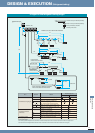
DESIGN & EXECUTION
DESIGN & EXECUTION
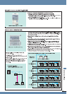
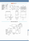
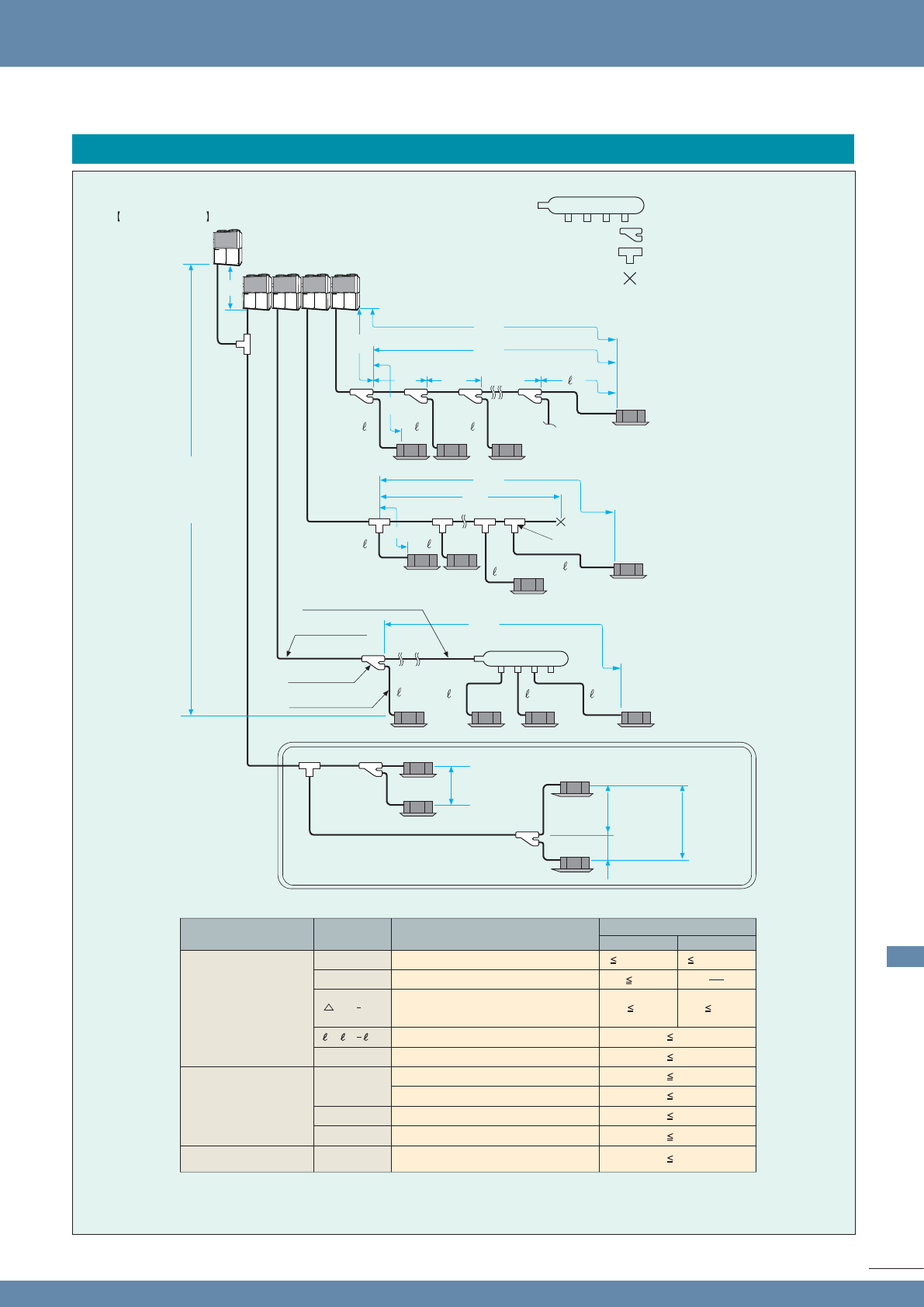
(Refrigerant tubing)
: Header tube (purchased separately)
: Branch tube (purchased separately)
: T-tee (provided by installer)
: Closed (pinch) weld
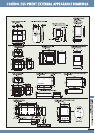
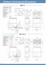
Distance (cm) from flammable materials
Outdoor unit
LA
L1
L2
LB
L4
L3
LA
H1
H3
L4
LC LG
L2
8
1 2
1 2
7
1
6 7 8
8
3
L2
T-tee
branch tube
Indoor unit
Unit main tube
Unit main tube
No. 1 branch
4 m or less
*Limit of elevation difference between
indoor units after the final branch
Over 2X
X
Over 4 m
(between unit branch tubes)
Unit branch tube
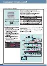
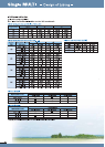
Item
Allowable tubing length
L1
40
2 way 3 way
Maximum allowable tubing length
L5
Maximum length between outdoor units
If outdoor unit is below
If outdoor unit is above
Difference between longest and
shortest tubing lengths after the
No. 1 branch (first branching point)
Maximum length of each branch tube
Maximum difference between indoor units
Maximum length from the first
tees to the front seal
H1
H2
H3
L3
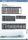
Allowable elevation
difference
Allowable header
tubing length
Symbol Details
Actual length (m)
30
10
4
170 (200)*
1
120 (145)*
1
LA Maximum main tubing length 120
35*
2
15*
3
2
30
50
(*2)
If cooling mode is expected to be used when the external temperature is 10˚C or below, install so the maximum length is 30 m.
(*1)
Equivalent length
(*3)
Install so that the height difference between indoor units after the final branch is within the limits shown in the figure.
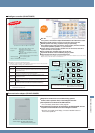
In regard to the refrigerant tubing length
L(L2 L4)
1, 82,
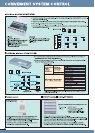
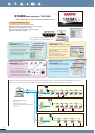
System Example
STAIMS
Maximum difference between outdoor units
GHP_BRO_Z1.indd 65 03.07.2008 17:31:56 Uhr