


5
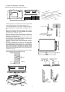
2. HOW TO INSTALL THE UNIT
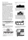
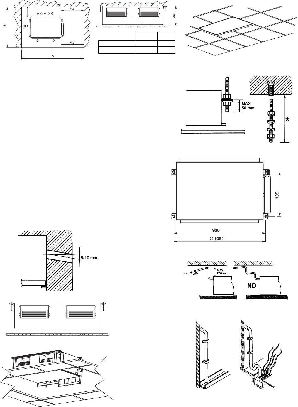
Fig. 2-1
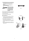
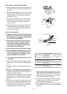
Minimum operation and maintenance area. (fig. 2-1)
Fig. 2-2
Fig. 2-4
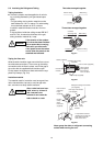
Find the space for the installation of the return air grille and
mark the opening to do. Cut the falseceiling. (fig. 2-2)
Use rawl plug suitable to the ceiling consistence and four
M10 threaded bars of suitable length (not supplied). (fig. 2-
3)
Mark on the ceiling the holes for the hanging rods, verify the
distance of the centres. The value included in the brackets
is referred to the model X18. (fig. 2-4)
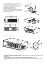
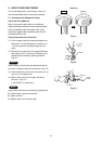
Drill a 80 mm diameter hole, for the passage of refrigeration
pipework, condensate pipework and electrical cable. Insert
a PVC pipe in the wall. (fig. 2-5)
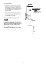
Secure the unit in position with locknuts and washers, level
the unit, keeping the right distance from the falseceiling for
the installation of return air grille. (fig. 2-6)
Foresee a removable panel of the falseceiling for servicing.
(fig. 2-7)
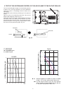
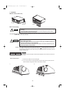
The unit is supplied with PVC hose from the condensate
pump. Maximum pump lift is 250 mm over the unit. Convoy
the condensate with a positive slope (min. 1:100) to the out-
side. The highest point in the condensate pipework should
be as close to the unit as possible. This prevents a large
volume of water draining back into the unit when it is
switched off. (fig. 2-8)
Convoy the condensate to the outside with a positive slope,
from a trap at the end if necessary. (fig. 2-9)
300
Fig. 2-3
Fig. 2-5
Fig. 2-6
Fig. 2-7
Fig. 2-8
Fig. 2-9
7/9/12 1500 1100
16/18/22 1700 1100
AB