


40
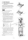
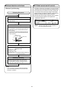
■ If self-diagnostics function fails to operate
<Checking the indoor and outdoor units>
■ Checking the indoor unit
■ Checking the outdoor unit
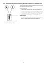
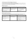
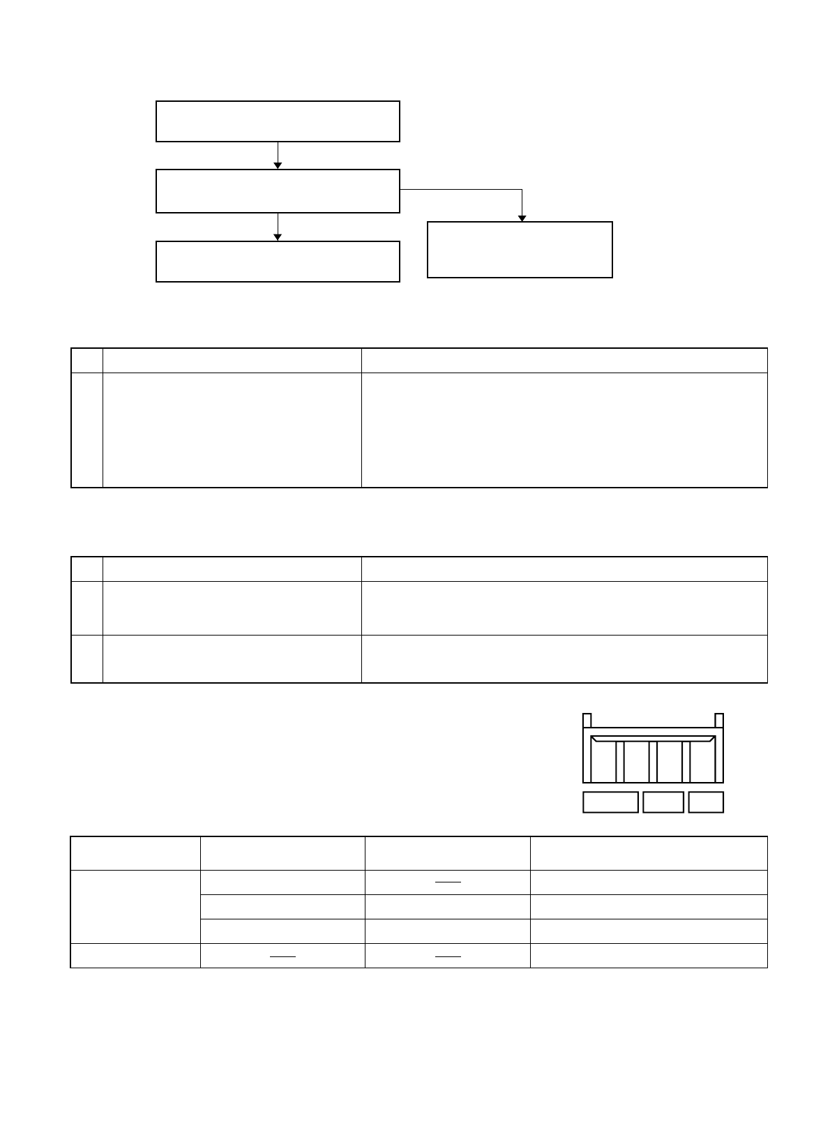
■ Checking serial communications
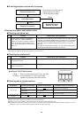
Check the indoor unit.
Is the fuse blown?
ControlNo. Check items (unit operation)
Replace the controller.
Replace the circuit
board or the fuse.
• No indicators illuminate and the
indoor fan does not rotate.
• Check the power voltage.
Use the remote controller to operate the
unit in “TEST run” mode. To determine
whether the mode is currently in “TEST run”
mode, check the 3 indicator lamps on the
unit. If all 3 are blinking, the current mode is
“TEST run.”
● If there are no problems with the above, then check the outdoor unit.
● For the “Test run” procedure, refer to 7.4 “How to Test Run the Air Conditioner.”
1
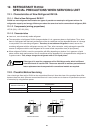
• The rated voltage must be present between inter-unit cables 1 and 2.
• Connect a 5 kΩ resistor between inter-unit cables 2 and 4. When the
voltage at both ends is measured, approximately 12–15 V DC must
be output and the multimeter pointer must bounce once every 8
seconds.
Or instead of measuring the voltage, you can insert an LED jig and
check that the LED flickers once every 8 seconds.
ControlNo. Check items (unit operation)
Short-circuit terminals 2 and 4 on
the indoor unit terminal base.
Initial self-
diagnostics
Probable location of malfunction
Short-circuit terminals 2 and 4 on
the indoor unit terminal base.
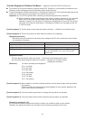
Apply the rated voltage between outdoor
unit terminals 1 and 2.
● If there are no problems with the above, then check the indoor unit.
● Turn the power OFF before performing short circuiting procedures.
● Refer to the previous pages when performing system self-diagnostics.
● So that the check can be made quickly, indicators blink at first communication after power ON.
● Before performing the above checks, perform “TEST run” operation, and check that the rated voltage is output to terminals 1 and 2 on
the outdoor unit. If it is not output, there is a failure related to the indoor unit power.
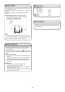
1 • The control panel LED (red) must illuminate.
Short-circuit the outdoor unit COM terminal
to the T-RUN terminal.
2 • The compressor, fan motor, and 4-way valve must all turn ON.
Normal
Blown
→ Control 1
No change Indoor unit circuit board failure
Outdoor unit circuit board failure
Failure (open circuit, contact failure, etc.)
in the inter-unit wiring
Outdoor unit circuit board failure
Change: (1) and (3) illuminate,
and (2) blinks.
(1) illuminates
Change: (1) and (3) illuminate,
and (3) blinks.
Change: (1) and (3) illuminate,
and (2) blinks.
Change: (1) illuminates
(1) and (3) illuminate,
and blinks.
→ Control 2
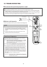
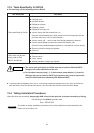
● Using the TEST/T-RUN terminals
T-RUN : Test run (compressor and fan motor turn ON).
TEST/MV : Compresses time to 1/60th (accelerates
operation by 60 times faster than normal).
TEST/T-RUN terminals
(TEST)/MV
T-RUN COM