


43
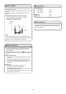
11-1. Measurement of Insulation
Resistance
●
The insulation is in good condition if the resistance
exceeds 1MΩ.
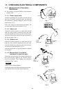
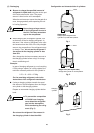
11-1-1. Power supply cord
Clamp the grounding wire of power cord with the lead
clip of the insulation resistance tester and measure
the resistance by placing a probe on either of the two
power wires. (Fig. 1)
Then also measure the resistance between the
grounding and other power terminals. (Fig. 1)
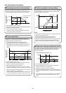
11-1-2. Indoor unit
Clamp an aluminum plate fin or copper tube with the
lead clip of the insulation resistance tester and mea-
sure the resistance by placing a probe on each termi-
nal screw where power supply lines are connected on
the terminal plate. (Fig. 2)
11-1-3. Outdoor unit
Clamp an aluminum plate fin or copper tube with the
lead clip of the insulation resistance tester and mea-
sure the resistance by placing a probe on each termi-
nal screw on the terminal plate. (Fig. 2)
Note that the ground line terminal should be skipped
for the check.
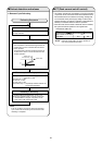
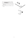
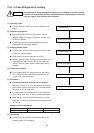
11-1-4. Measurement of insulation
resistance for electrical parts
Disconnect the lead wires of the desired electric part
from terminal plate, capacitor, etc. Similarly discon-
nect the connector. Then measure the insulation
resistance. (Figs. 3 and 4)
Refer to Electric Wiring Diagram.
If the probe cannot enter the poles because the hole
is too narrow then use a probe with a thinner pin.
NOTE
Insulation
tester
Probe
Clip
Ground wire
Fig. 1
Terminal plate
Copper
tube or
metallic part
Clip
Insulation
tester
Probe
Fig. 2
Copper
tube or
metallic part
Clip
Insulation
tester
Probe
Fig. 3
Clip
Insulation
tester
Probe
Metallic
part
From fan motor,
compressor and
other parts
Fig. 4
11. CHECKING ELECTRICAL COMPONENTS