


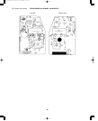
46
7-4. Recommended Wire Length
and Diameter
Regulations on wiring diameter differ from locality to
locality. For field wiring requirements, please refer to
your local electrical codes. Carefully observe these reg-
ulations when carrying out the installation.
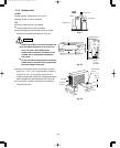
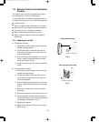
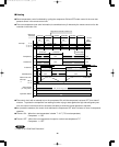
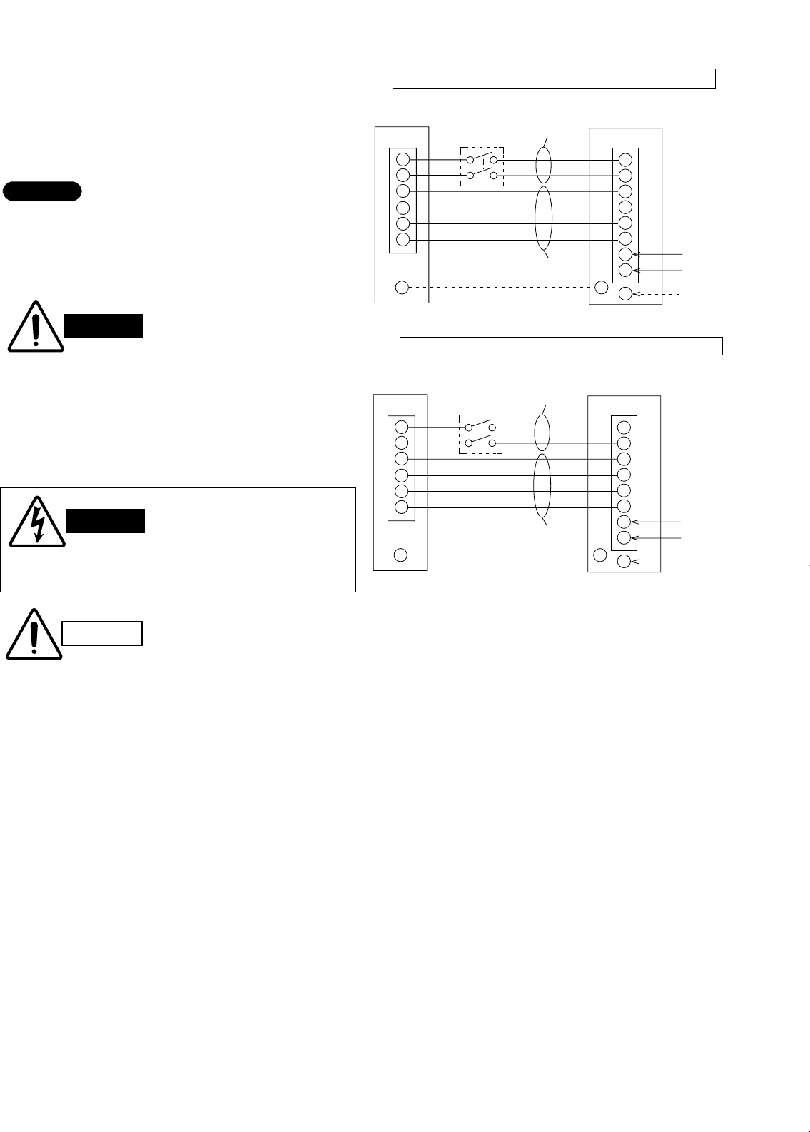
Refer to the wiring system diagram (Fig. 11)
Refer to your local codes or in the absence of local
codes with the National Electric Code: ANSI/NFPA70.
NOTE
INDOOR UNIT
Terminal
Disconnect
switch
(Field supply)
1
2
3
4
5
6
1
2
3
4
5
6
7
8
G
G
G
Grounding
line
(Inter-unit)
Power lines
(Inter-unit)
Control lines
Terminal
OUTDOOR UNIT
Power supply line
Single-phase, 115V
60Hz
L1
L2
INDOOR UNIT
Terminal
Disconnect
switch
(Field supply)
1
2
3
4
5
6
1
2
3
4
5
6
7
8
G
G
G
Grounding
line
(Inter-unit)
Power lines
(Inter-unit)
Control lines
Terminal
OUTDOOR UNIT
Power supply line
Single-phase, 230/208V
60Hz
L1
L2
Fig. 11
CAUTION
●
Be sure to connect the power supply line to the
outdoor unit as shown in the wiring diagram. The
indoor unit draws its power from the outdoor
unit.
WIRING SYSTEM DIAGRAM
WARNING
●
Be sure to comply with local codes on running
the wire from the outdoor unit to the indoor unit
(size of wire and wiring method, etc.).
●
Each wire must be firmly connected.
●
No wire should be allowed to touch refrigerant
tubing, the compressor, or any moving part.
●
To avoid the risk of electric shock, each air
conditioner unit must be grounded.
WARNING
CH0951, CH1251 Models
CH1852 Model
000-111 SM (18-68) 00.3.17 11:49 AM y[W 46