


– 32 –
SM830092
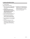
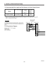
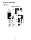
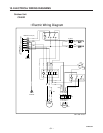
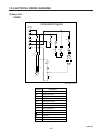
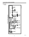
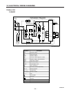
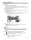
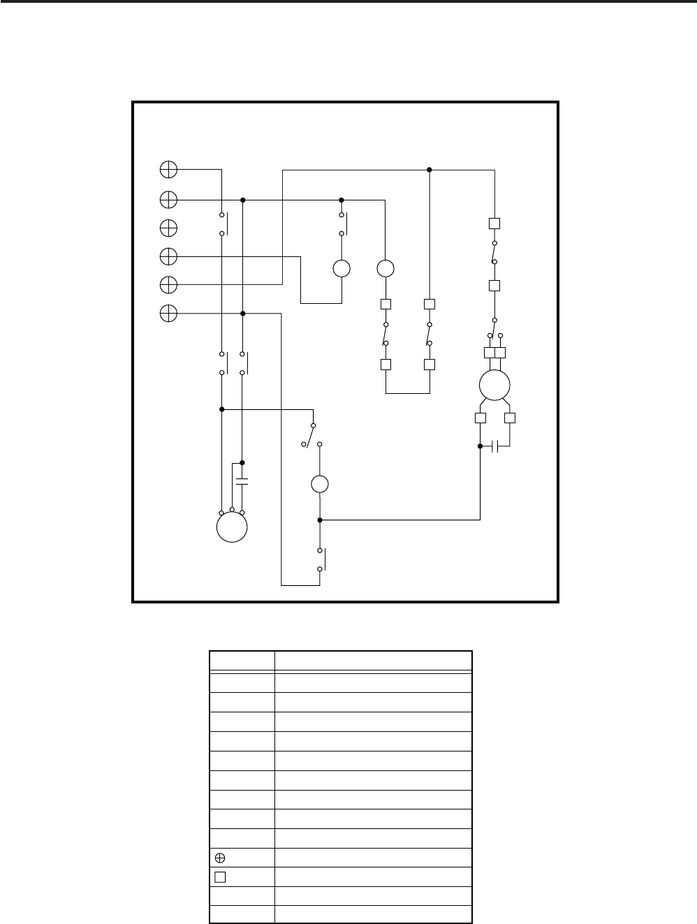
10. ELECTRICAL WIRING DIAGRAMS
2Y52C
1
2
2Y
TERMINAL
PLATE (6P)
2Y
RC2
63PH
C
LH
C
R
S
RC1
52C
– 1
– 2
1Y
1Y
HM
FMO
CM
65
12
49FO
52C
23S
• Schematic Diagram
Symbols Description
CM
FMO
49FO
52C
63PH
23S
RC1, 2
1Y, 2Y
Compressor Motor
Outdoor Fan Motor
Outdoor Fan Motor Thermal Protector
Compressor Motor Magnetic Contactor
High Pressure Switch
63PL Low Pressure Switch
Fan Speed Control Thermostat
Running Capacitor
Auxiliary Relay
Connector
Terminal Base
– G
– 4
– L1
– L2
1
2
2
63PL
1
854-2-5269-160-00-0
Outdoor Unit
C2462R