


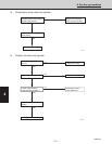
4. Service procedures
1
2
3
4
Section
– 76 –
SM830076
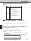
NOTE
Location of Sensor (Themistor)
Relationship between the sensor address and the location of sensor
Sensor Address
(CODE No.)
Indoor Unit 01 —
02 TH1 Indoor air suction Temp.
03 TH2 Indoor coil Temp. (E1)
04 TH3 Indoor coil Temp. (E2)
05 —
06 —
07 —
08 Electronic expansion valve open
09 —
Outdoor Unit 0A TH8 Discharge gas Temp.
0B —
0C —
0D TH7 Outdoor coil liquid Temp. (C2)
0E TH6 Outdoor coil liquid Temp. (C1)
0F —
10 —
11 —
12 —
13 —
14 —
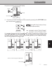
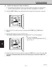
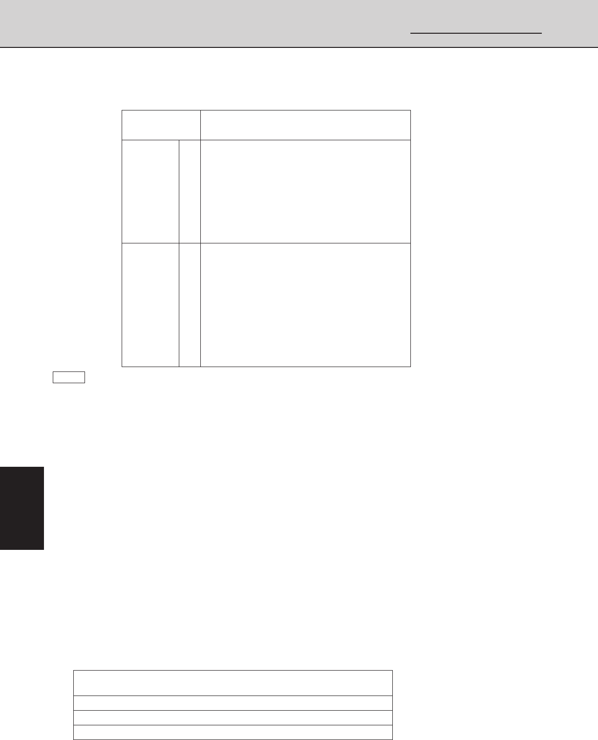
NORMAL DISPLAY
Display Change
SERVICE CHECK DISPLAY
Set temp. Code No.
UNIT No. UNIT No. (
Indoor unit address
)
Hours, Minutes Alarm Message
(
)
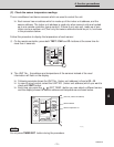
Refer to the table below for the relationship between the sensor address and the location of
the sensor.
In case there are no sensor equipped with the unit, “- - -” is shown on the display.
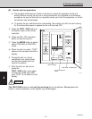
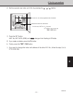
C Resetting the remote controller display to previous mode.
❏ To reset the display, press TEST / CHK button, then the remote controller will return
to previous mode.
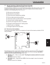
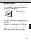
(D) Find out about past service problems
The remote controller can memorize the max. 4 most recent alarm messages, so you can
see problems the unit has had, if any. Knowing what has already occurred and been fixed
helps you to know what to check at present.
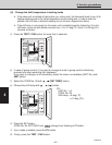
❏ This function is usable even if the unit is not working.
❏ To display the past error codes, follow the procedure below.
Procedure:
a On the remote controller, press both TEST / CHK and SET buttons at the same time for
more than 4 seconds.
b Once in this mode, display changes from the normal display to service check display as
shown in the table below: