


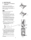
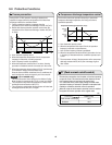
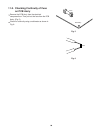
10-3. Checking the Indoor and Outdoor Units
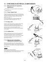
(1) Checking the indoor unit
(2) Checking the outdoor unit
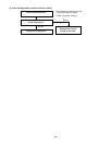
(3) Checking the serial communications
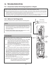
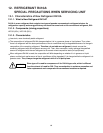
Using the TEST/T-RUN terminals
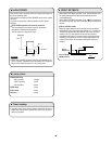
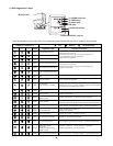
ControlNo. Check items (unit operation)
T-RUN : Test run (compressor and fan motor turn ON).
TEST/MV : Compresses time to 1/60th (accelerates
operation by 60 times faster than normal).
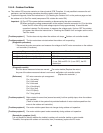
Use the remote controller to operate the
unit in "TEST run" mode. To determine
whether the mode is currently in
"TEST run" mode, check the 3 indicator
lamps on the unit. If all 3 are blinking,
the current mode is "TEST run."
If there are no problems with the above, then check the outdoor unit.
1
The rated voltage must be present between inter-unit wirings 1 and 2.
Connect a 5 k ohm resistor between inter-unit wirings 2 and 3. When the
voltage at both ends is measured, approximately 12 to 15V DC must
be output and the multimeter pointer must bounce once every 8
seconds.
Or instead of measuring the voltage, you can insert an LED jig and
check that the LED flickers once every 8 seconds.
•
•
ControlNo. Check items (unit operation)
Apply the rated voltage between outdoor
unit terminals 1 and 2.
If there are no problems with the above, then check the indoor unit.
Turn the power OFF before performing short circuiting procedures.
Refer to the previous pages when performing system self-diagnostics.
So that the check can be made quickly, indicators blink at first communication after power ON.
Before performing the above checks, perform “TEST run” operation, and check that the rated voltage is output to terminals 1 and 2
on the outdoor unit. If it is not output, there is a failure related to the indoor unit power.
1 The control panel LED (red) must illuminate.
Short-circuit the outdoor unit COM terminal
to the T-RUN terminal.
2 The compressor, fan motor, and 4-way valve must all turn on.
•
•
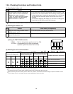
TEST/T-RUN terminals
(TEST)/MV T-RUN COM
For the "Test run" procedure, refer to 7.4" How to Test Run the Air Conditioner".
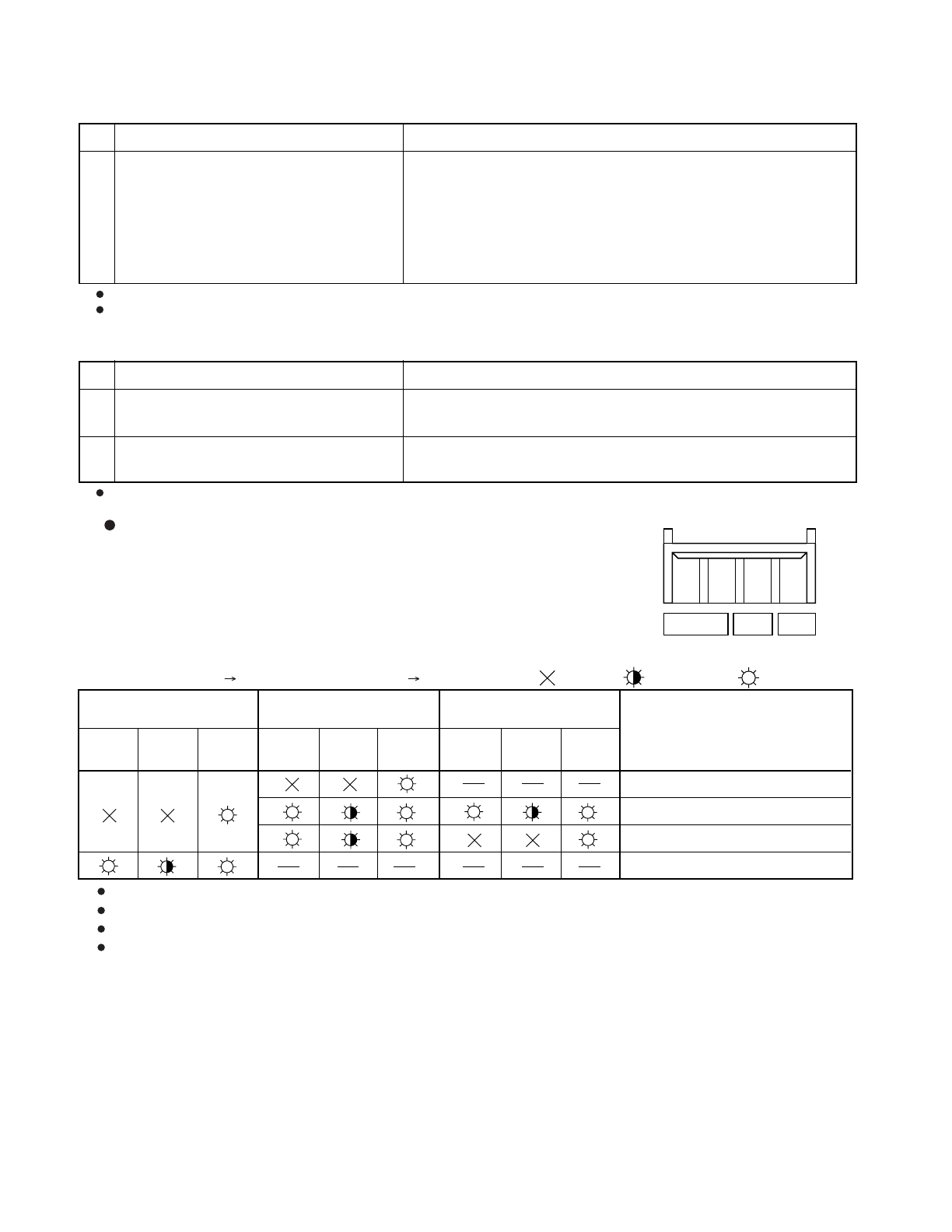
Probable location of malfunction
Indoor unit circuit board failure
Outdoor unit circuit board failure
Failure (open circuit, contact failure, etc.)
in the inter-unit wirings
Outdoor unit circuit board failure
Short-circuit terminals 2 and 3 on
the outdoor unit terminal plate.
Short-circuit terminals 2 and 3 on
the indoor unit terminal plate.
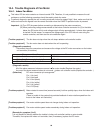
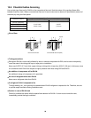
Initial self-diagnostics
Control 1 Control 2
....
OFF
....
Blinking
....
Illuminated
Quiet
( 3 )
Timer
( 2 )
Operation
( 1 )
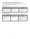
Quiet
( 3 )
Timer
( 2 )
Operation
( 1 )
Quiet
( 3 )
Timer
( 2 )
Operation
( 1 )
51