


English17
INSTALLATION AND EXTERNAL CONNECTION
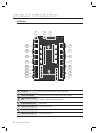
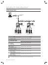
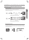
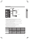
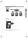
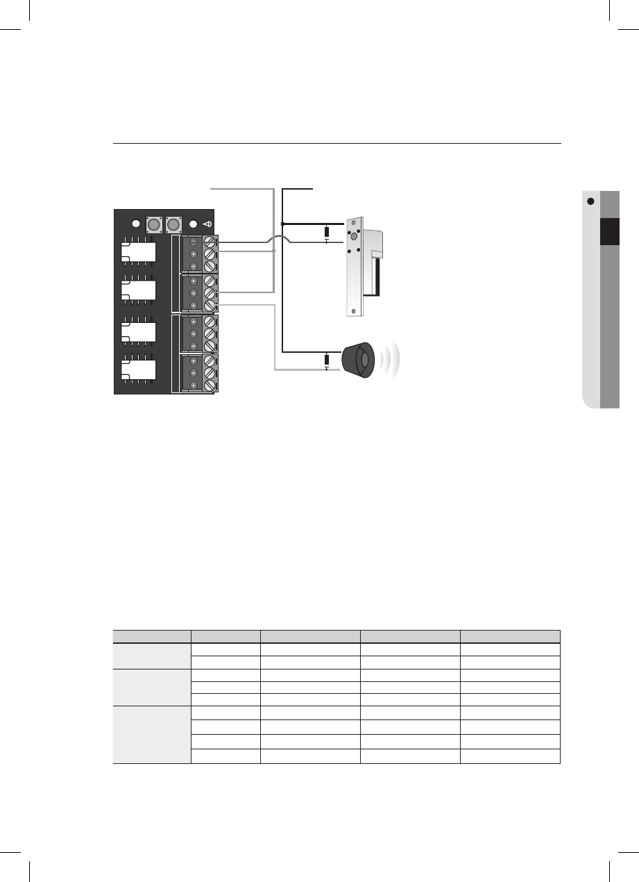
Output Connection
- If the door lock is in POWER FAIL SAFE mode: (Door 1: Relay #1, Door 2: Relay #3)
Connect the COM line of the Door Lock relay to DC +12V.
Connect the plus (+) line of the Door Lock to the Normal Close (NC) line of the Door Lock relay.
Connect the minus (-) line of the Door Lock to GND (-).
- If the Door Lock is in POWER FAIL SECURE mode: (Door 1: Relay #1, Door 2: Relay #3)
Connect the COM line of the relay to DC +12V.
Connect the plus (+) line of the Door Lock to the Normal Open (NO) line of the Door Lock relay.
Connect the minus (-) line of the Door Lock to GND (-).
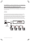
Alarm Device Connection (Door 1 Alarm: Relay #2, Door 2 Alarm: Relay #4)
Connect the COM line of the alarm device relay to DC +12V.
Connect the plus (+) line of the alarm device to the NO line of the alarm device relay.
Connect the minus (-) line of the alarm device to GND (-).
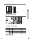
Door Number Door Lock Alarm Device Note
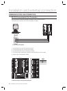
Two Door Control
1 Relay Output #1 Relay Output #2
2 Relay Output #3 Relay Output #4
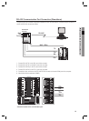
Three Door Control
1 Relay Output #1 Relay Output #2
2 Relay Output #8 Relay Output #9 I/O Board
3 Relay Output #10 Relay Output #11 I/O Board
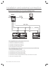
Four Door Control
1 Relay Output #1 Relay Output #2
2 Relay Output #3 Relay Output #4
3 Relay Output #8 Relay Output #9 I/O Board
4 Relay Output #10 Relay Output #11 I/O Board
1.
2.
3.
1.
2.
3.
1.
2.
3.
Door Lock
POWER FAIL SAFE
POWER FAIL SECURE
GND
Alarm Device
DC +12V GND
NC
COM
COM
NO