


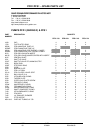

PFD1/PFS1 – OPERATING INSTRUCTIONS
INDEX DATE N°
03 27/09/01 DC01020US
8/11
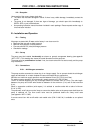
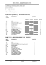
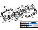
VI.3.3 – Replacing the central shaft and shaft composite rings
Follow the same steps described in V1.3.2 until 8) then:
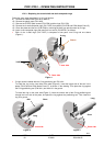
9) Remove the central shaft (P/N 2615, Mark D),
10) Remove the plastic caps (P/N 1028),
11) Remove the C-PEEK plate screws (P/N 2729) and the rings (P/N 1720),
12) Remove the 4 shaft composite rings (P/N 7135F) from plates (P/N 2709 and 2728, Marks B and C),
13) Clean the plates and the core (P/N 2708) by removing the dust from previous wear by O.rings,
14) Insert 4 new composite rings with tools from our tool kit (P/N KPFD1) as follows:
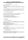
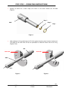
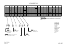
• Each of the 4 shaft rings (P/N 7135F) is composed of two parts: one O.ring and one sleeve
(Figure 1):
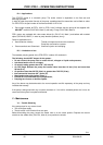
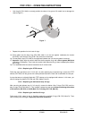
• O.rings can be installed with the O.ring positioning tool P/N 1641.
To install the ring on the inner side of the plate (Figure 2), insert the longer side of the tool in the
plates (P/N 2709 and 2728, Marks B and C), as shown in the drawing. Then place the ring against
the O.ring positioning tool (P/N 1641) and insert it in the groove.
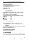
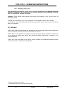
To install the ring on the outer side (Figure 3), insert the shorter side of the O.ring positioning tool
through the inner side of the plate, and place the ring against the positioning tool. Then insert the
ring in its groove.
Figure 1
7135F
Sleeve
O.ring
Inner side
Outer side
Figure 2
Long
Short
1641
Inner side
Figure 3
Long
Short
Outer side