


PFD4/PFS4 – OPERATING INSTRUCTIONS
INDEX DATE N°
03 22/04/02 DC04020US
3/8
II.2 – Reception
Upon receipt of the pump, please check that:
• The carton has not been damaged in transit. If there is any visible damage, immediately contact
the carrier.
• The pump is not damaged. If there are signs of damage, you should report this immediately to
SGPPL ASTI or your local distributor.
• An operating instruction manual has been included in each package. Please request another copy
if it has not been included.
III – Installation and operation
III.1 – Testing
All pumps are tested with DI water at the factory in our clean room for:
• Maximum flow rate with no back pressure
• Minimum flow rate with no back pressure
• Flow rate with 58 PSI (4 bar) discharge pressure
• Checked for leakage
III.2 – Set up
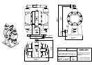
The pump must be installed horizontally as shown on general arrangement drawing
(see appendix “APP 4 EXT”). This drawing also shows the overall dimensions of the pump etc.
The pump must be installed on its feet. If not, the check valves will not seat correctly and the pump
may malfunction.
III.3 – Connections
III.3.1 – Air/Nitrogen connections
The pump must be connected to a clean dry air or nitrogen supply. On no account should the
air/nitrogen supply be lubricated, oil or water droplets will cause the shuttle valve to malfunction.
Minimum and maximum supply pressure must be between 29 and 72.5 PSI (2 and 5 bar).
For optimum pump operation, we recommend a supply pressure of 58 PSI (4 bar).
The ID of the tube supplying the dry air/nitrogen should not exceed 3/8” (10 mm). The tube length
between the pump and on/off valve should be between minimum 10 feet (3 m) and maximum 19 feet
(6 m).
When in aggressive conditions (acid vapors), it is advised to canalize outlet with a tube minimum
ID 5/8” (15 mm).
The pneumatic on/off valve must be 3-way to ensure the shuttle valve on the pump resets itself when
the pump is switched off. The flow control valve must be positioned before the 3-way on/off valve
(see appendix “APP 4 CAB”).
A remote control box with on/off switch and a needle valve (P/N 24 000 04) is available as an optional
extra.
III.3.2 – Fluid connections
The pump is self-priming. The inlet is at the bottom and the outlet at the top.
Two optional fittings are available:
• PFD4 322 or PFS4 322: pump is supplied with flared fittings suitable for 7/8”x1” (22x25 mm)
TEFLON
®
tube. The tube needs to be flared prior to fitting using SGPPL ASTI Forming Tool
(P/N MF12228).