


switched contacts at the doorbell chime module to the connections
labeled “DB1,” “DB2” and “DB3” on the DIM-1. This connects up to 3
separate doorbell buttons to the DIM-1. Refer to Figure 1. Note that the
connectors can be unplugged for easy wiring.
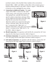
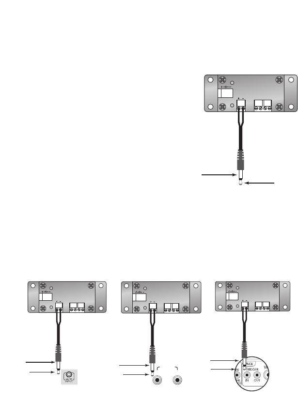
4) Connection to Multi-zone System: The trigger
output of the DIM-1 connects to the audio
system using a 1/8" mono plug. Connect the
mono plug to the controller (see below for
specific system connections) and snip off the
excess length from the other end of the cable.
Strip the two wires from this end and
determine which wire comes from the tip by
using a continuity meter. The wire from the
tip (+) connects to the "TRIG OUT (+)"
terminal of the DIM-1. The other wire from the
sleeve (-) connects to the "TRIG OUT (-)" of
the DIM-1. Refer to Figure 2.
4a) PR-4Zi Connection: For operation with the PR-4Zi, connect the 1/8” mini
plug into the Mute Input connection. Refer to Figure 3.
4b) CAi Series Connection: For operation with the CA4.4i/CA6.4i, connect the
1/8” mini plug into the Mute Input connection. Refer to Figure 4.
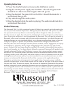
4c) CAV Series Connection: For operation with the CAV6.6, connect the 1/8”
mini plug into the Page Trigger Input connection. Refer to Figure 5.
TRIG OUT
TRIG
+12V DC
DB3
DB2
DB1
TRANS
POWER
DOORBELL INTERFACE
(-) Sleeve
(+) Tip
TRIG OUT
TRIG
+12V DC
DB3
DB2
DB1
TRANS
POWER
DOORBELL INTERFACE
(-) Sleeve
(+) Tip
Figure 2
Figure 3
TRIG OUT
TRIG
+12V DC
DB3
DB2
DB1
TRANS
POWER
DOORBELL INTERFACE
(-) Sleeve
(+) Tip
MUTE
IN OUT
Figure 4
TRIG OUT
TRIG
+12V DC
DB3
DB2
DB1
TRANS
POWER
DOORBELL INTERFACE
(-) Sleeve
(+) Tip
Figure 5
PR-4Zi CAi Series
CAV6.6