


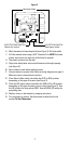
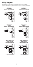
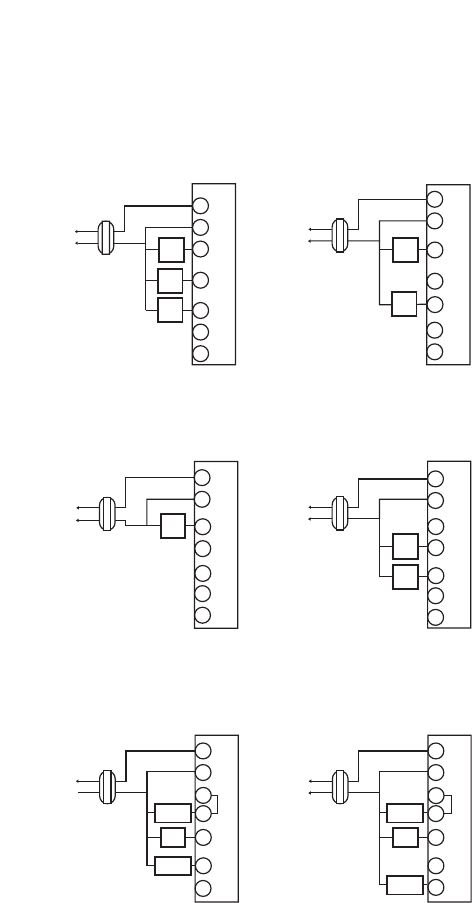
Wiring Diagrams
The following is just a sample of the most common types of HVAC
systems. Refer to your system’s installation manual for wiring information.
5
Hot
Heating
Control
Cooling
Control
Transformer
T
H
E
R
M
O
S
T
A
T
W1
C
R
Y1
G
O
B
24 VAC
120 VAC
Hot
Heating
Control
Fan
Control
Transformer
24 VAC
120 VAC
Hot
Heating
Control
Transformer
24 VAC
120 VAC
HEAT/COOL
4-WIRE
SINGLE TRANSFORMER
HEAT ONLY
2-WIRE
SINGLE TRANSFORMER
HEAT ONLY
SINGLE TRANSFORMER
3-WIRE
Hot
Cooling
Control
Fan
Control
Transformer
24 VAC
120 VAC
COOL ONLY
3-WIRE
SINGLE TRANSFORMER
W1
Y1
G
W1
Y1
G
W1
Y1
G
Hot
Compressor
Contactor
Transformer
24 VAC
120 VAC
HEAT PUMP WITH
COOL ACTIVE
REVERSING VALVE
W1
Y1
B
G
O
Hot
Transformer
24 VAC
120 VAC
HEAT PUMP WITH
HEAT ACTIVE
REVERSING VALVE
W1
T
H
E
R
M
O
S
T
A
T
T
H
E
R
M
O
S
T
A
T
T
H
E
R
M
O
S
T
A
T
T
H
E
R
M
O
S
T
A
T
T
H
E
R
M
O
S
T
A
T
NOTE: When switched to HP mode,
W1 is connected internally to Y1.
NOTE: When switched to HP mode,
W1 is connected internally to Y1.
O
B
O
B
O
B
Reversing
Valve
Fan
Relay
Compressor
Contactor
Y1
G
O
B
Reversing
Valve
Fan
Relay
Fan
Control
C
R
C
R
C
R
C
R
C
R