


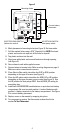
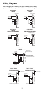
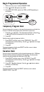
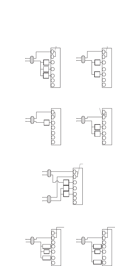
Wiring Diagrams
The following is just a sample of the most common types of HVAC
systems. Refer to your system’s installation manual for wiring information.
5
Hot
Heating
Control
Fan
Control
Cooling
Control
Heating
Control
(COOLING)
Transformer
(HEATING)
Transformer
Transformer
T
H
E
R
M
O
S
T
A
T
RH
RC
W1
Y1
G
O
B
24 VAC
120 VAC
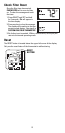
Hot
Heating
Control
Fan
Control
Transformer
24 VAC
120 VAC
Hot
Heating
Control
Transformer
24 VAC
120 VAC
Hot
120 VAC 24 VAC
24 VAC
Hot
120 VAC
HEAT/COOL
4-WIRE
SINGLE TRANSFORMER
HEAT ONLY
2-WIRE
SINGLE TRANSFORMER
HEAT ONLY
SINGLE TRANSFORMER
3-WIRE
Factory-Installed
Jumper
Hot
Cooling
Control
Fan
Control
Transformer
24 VAC
120 VAC
COOL ONLY
3-WIRE
SINGLE TRANSFORMER
Cooling
Control
HEAT/COOL
5-WIRE
TWO TRANSFORMER
RH
RC
W1
Y1
G
Factory-Installed
Jumper
RH
RC
W1
Y1
G
NOTE: Disconnect
factory installed jumper.
RH
RC
W1
Y1
G
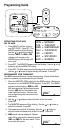
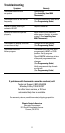
Hot
Compressor
Contactor
Transformer
24 VAC
120 VAC
HEAT PUMP WITH
COOL ACTIVE
REVERSING VALVE
RH
RC
W1
Y1
B
G
O
RC
RH
W1
Y1
G
CAUTION: Both transformers
must be in phase or damage
may result.
to the equipment and thermostat
Hot
Transformer
24 VAC
120 VAC
HEAT PUMP WITH
HEAT ACTIVE
REVERSING VALVE
RH
RC
W1
NOTE: Factory
Installed Jumper
NOTE: Factory
Installed Jumper
T
H
E
R
M
O
S
T
A
T
T
H
E
R
M
O
S
T
A
T
T
H
E
R
M
O
S
T
A
T
T
H
E
R
M
O
S
T
A
T
T
H
E
R
M
O
S
T
A
T
T
H
E
R
M
O
S
T
A
T
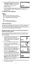
NOTE: Remove factory
installed jumper
NOTE: Make sure the HP switch
is in the HP position
NOTE: Make sure the HP switch
is in the HP position
O
B
O
B
O
B
O
B
Fan
Relay
Reversing
Valve
Fan
Relay
Compressor
Contactor
Y1
G
O
B
Reversing
Valve
Fan
Relay