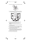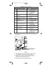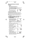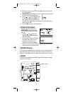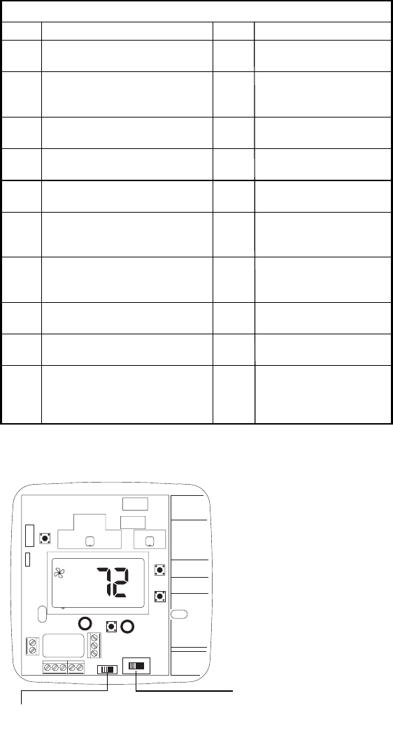
15. Set the Electric/Gas switch to either GAS for a gas/oil heating
system or ELEC for an electric heating system (Figure 5).
16. Set the HP option switch to either the HP for heat pump or
NON_HP for furnace applications (Figure 5).
17. Replace thermostat cover by snapping into place.
7
R
L
C
Y2
W2/E
GOBY1W1
ELEC GAS
NON_HP HP
°
F
Figure 5
TERMINAL LEGEND - 8425
TERM EQUIPMENT TO CONNECT REQ? TERMINAL FUNCTION
R 24 VAC hot connection Yes For input of 24VAC hot
side of transformer
C 24 VAC common connection Yes For input of 24VAC
common side of
transformer
L System fault indicator No For connection of system
connection fault indicator (if present)
W1 First stage connection for No* Energizes on a call
non heat-pump applications for heat
Y2 Second stage cooling No Energizes on a call for
connection second stage cooling
Y1 First stage compressor Yes Energizes on a call for
connection first stage of heating
and cooling
W2/E Second stage heat or Yes* Energizes on a call for
Emergency heat connection second stage or
emergency heat
B Heat active reversing Yes** Energizes when in the
valve connection HEAT or EM modes
O Cool active reversing Yes** Energizes when in the
valve connection COOL mode
G Indoor fan connection Yes Energizes with E & Y1, Y2
and W2 terminals or with
FAN option switched to
the ON position
* Do not connect W1 in heat pump applications. Connect auxiliary heat to W2/E.
** Most heat pump systems will have a cool active or a heat active reversing valve. Use the
appropriate terminal.
ELECTRIC/GAS SWITCH
Selects fan control.
HP OPTION SWITCH
Heat pump switch.
110-1090B.qxd 3/4/05 3:58 PM Page 7


