


SECTION 8: OPTIONAL HEATER ACCESSORIES
27
SECTION 8: OPTIONAL HEATER ACCESSORIES
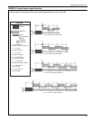
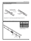
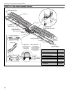
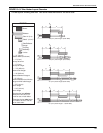
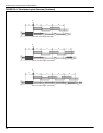
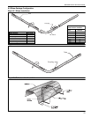
8.1 U-Tube Configuration
The heaters are approved for optional U-Tu be
configurations. This installation requires 1 or 2 U-
Tu be packages depending on configuration desired.
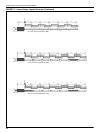
Shown below is an example of a typical 80' (24 m) U-
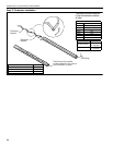
Tu be configuration. The U-Tube may be installed in
either a standard horizontal position or in an opposite
45° position as shown below. When designing a U-
Tu be configuration, the following additional rules
must be adhered to:
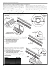
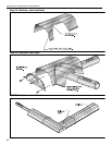
• A minimum of 10' (3 m) on TF-120/160 and a min-
imum of 15' (4.5 m) on TF-200/250/300/ 350/380
is required between the burner and the U-Tube.
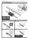
• The correct turbulator (See Page 24, Step 7.5)
must be installed in the last standard section of
tube.
• The burner must never be operated in a tilted
position.
• When installed in a full 45° position, the burner
must be installed on the lower side.
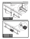
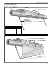
• The heater mu
st be properly supported at all loca-
tions. See Page 29, Figure 19.
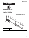
WARNING
Cut/Pinch Hazard
Wear protective gear during installation,
operation and service.
Edges are sharp.
Failure to follow these instructions can result
in injury.