


TF-SERIES INSTALLATION, OPERATION AND SERVICE MANUAL
6
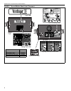
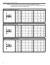
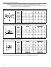
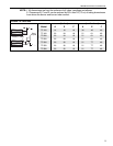
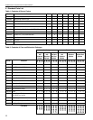
NOTE: 1. All dimensions are from the surfaces of all tubes, couplings and elbows.
2. Clearances B, C and D can be reduced by 50% after 25' (7.5 m) of tubing downstream
from where the burner and burner tube connect.
FIGURE 3: STANDARD REFLECTOR
(inches) (centimeters)
Model ABCDABCD
TF-120 6 35 63 35 16 89 161 89
TF-160 6 386638169716897
TF-200 6 40 71 40 16 102 181 102
TF-250 6 46 77 46 16 117 196 117
TF-300 6 50 80 50 16 127 204 127
TF-350 8 52 82 52 21 133 209 133
TF-380 8 52 82 52 21 133 209 133
FIGURE 4: ONE SIDE REFLECTOR
(inches) (centimeters)
Model ABCDABCD
TF-120 6 9 63 47 16 23 161 120
TF-160 6 9 70 54 16 23 178 138
TF-200 6 9 77 59 16 23 196 150
TF-250 6 9 83 65 16 23 211 166
TF-300 6 9 86 69 16 23 219 176
TF-350 8 9 88 73 21 23 224 186
TF-380 8 9 88 73 21 23 224 186
A
C
D
B
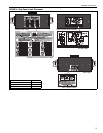
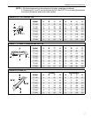
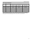
FIGURE 5: TWO SIDE REFLECTORS
(inches) (centimeters)
Model ABCDABCD
TF-120 6 23 66 23 16 59 168 59
TF-160 6 25 72 25 16 64 183 64
TF-200 6 27 78 27 16 69 199 69
TF-250 6 328432168221482
TF-300 6 35 88 35 16 89 224 89
TF-350 8 40914021102232102
TF-380 8 40 91 40 21 102 232 102
A
C
D
B