


© 2005
All rights reserved. No part of this work covered by the copyrights herein may be reproduced
or copied in any form or by any means - graphic, electronic, or mechanical, including
photocopying, recording, taping or information storage and retrieval systems - without the
written permission of Roberts-Gordon.
TABLE OF CONTENTS
SECTION 1: Heater Safety......................................................1
1.1 Manpower Requirements .............................................1
SECTION 2: Installer Responsibility .....................................2
2.1 Wall Tag.......................................................................2
2.2 Corrosive Chemicals....................................................2
2.3 National Standards and Applicable Codes ..................2
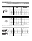
SECTION 3: Critical Considerations......................................3
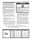
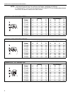
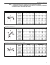
3.1 Required Clearances to Combustibles.........................3
SECTION 4: National Standards and Applicable Codes .....7
4.1 Gas Codes...................................................................7
4.2 Aircraft Hangars ...........................................................7
4.3 Public Garages ............................................................7
4.4 Electrical ......................................................................7
4.5 Venting.........................................................................7
4.6 High Altitude ................................................................7
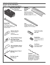
SECTION 5: Major Components ............................................8
5.1 Standard Parts List ......................................................9
SECTION 6: Suggested Layouts.......................................... 11
6.1 TF-380 - 4 Elbow Design (Common Vent) ................. 11
6.2 TF-350 - 4 Elbow Design (Common Vent) ................. 11
6.3 TF-300 - Double "U" Design (Common Vent) ............ 11
6.4 TF-160 - Single Elbow Design (Individual Vents).......12
6.5 TF-160 Double "L" Design (Individual Vents).............12
6.6 TF-250 - Combination "L" and "U" Design
(Individual Vents) ....................................................... 12
SECTION 7: Heater Installation............................................ 13
7.1 Burner Tube Installation ............................................18
7.2 Burner Installation......................................................18
7.3 Tube Clamp Package Installation..............................19
7.4 Coupling and Tube Assembly....................................19
7.5 Turbulator Installation ................................................21
7.6 Reflector Installation ..................................................21
SECTION 8: Optional Heater Accessories..........................23
8.1 U-Tube Configuration.................................................23
8.2 Elbow Package Configuration....................................26
8.3 Reflector Side Extension............................................28
8.4 Lower Clearance Shield Installation ..........................29
8.5 Two-Foot Decorative Grille Installation.......................29
8.6 One-Foot Decorative Grille Installation......................31
8.7 Protective Grille Installation........................................33
SECTION 9: Venting..............................................................34
9.1 Venting Requirements................................................34
9.2 Horizontal Ventilation 4" (10 cm) Pipe........................35
9.3 Vertical Ventilation 4" (10 cm) Pipe............................35
9.4 Flexible Boot Installation (Single Vent) ......................36
9.5 Common Sidewall Venting.........................................36
9.6 Vertical Ventilation 6" (15 cm) Pipe ...........................37
9.7 Flexible Boot Installation (Common Vent)..................37
9.8 Outside Combustion Air Supply.................................38
SECTION 10: Gas Piping...................................................... 40
SECTION 11: Wiring.............................................................. 41
11.1 Line Voltage Thermostat Wiring ............................... 41
11.2 Low Voltage Thermostat and Relay Wiring............... 42
11.3 Internal Wiring .......................................................... 42
11.4 Ladder Diagram....................................................... 43
11.5 Electrical Connection to the Burner.......................... 43
SECTION 12: Operation and Maintenance.......................... 44
12.1 Sequence of Operation............................................ 44
12.2 To Shut Off Heater................................................... 44
12.3 To Start Heater ........................................................ 44
12.4 Pre-Season Maintenance and Annual Inspection.... 44
12.5 Maintenance Checklist............................................. 45
SECTION 13: Troubleshooting............................................. 47
13.1 Troubleshooting Flow Chart..................................... 47
13.2 Manifold Gas Pressure Setting ................................ 49
SECTION 14: Replacement Parts ........................................ 50
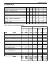
SECTION 15: General Specifications.................................. 52
15.1 Material Specification............................................... 52
15.2 Heater Specifications............................................... 52
15.3 Suspension Specifications....................................... 52
15.4 Controls Specifications ............................................ 52
SECTION 16: The ROBERTS GORDON
®
VANTAGE
®
TF
Warranty ................................................................................ 53
Printed in U.S.A.