


SECTION 4: TYPICAL EXTERNAL WIRING DIAGRAMS
7
SECTION 4: TYPICAL EXTERNAL WIRING
DIAGRAMS
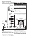
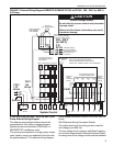
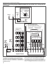
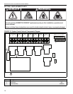
4.1 EP-100 or EP-201 120 V 1 Ø Pump External
Wiring Diagram
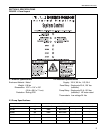
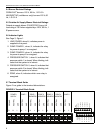
The external wiring diagram above shows the con-
nections for four zones of system burners. System
burners can be either CORAYVAC
®
or VANTAGE
®
NP
(multiburner only).
The zones are connected to a single pump, unless
zone 3 and/or zone 4 are selected to function with
the optional pump 2. The external wiring diagram
below shows connection to an EP-100 or EP-201 120
V 1 Ø pump.
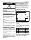
4.1.1 External Wiring Connection Details
The cable used for all the wiring must be rated for
line voltage up to 600 Vac.
The low voltage circuit conforms with Class 2 separa-
tion of circuit requirements. National Electrical Codes
®
for wiring class 2 low voltage circuits must be followed.
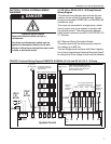
FIGURE 5: External Wiring Diagram ROBERTS GORDON
®
EP-100 and EP-201 120 V 1 Ø Pump
DANGER
Electrical Shock Hazard
Disconnect electric before service or
maintenance.
More than one disconnect switch may be
required to disconnect electric to the unit.
Failure to follow these instructions can result
in death or electrical shock.
System Control
R R R R PS 2PS 124 VAC
COM
24 VAC
COM
PS 1 PS 2WWWW
24 VAC
120 V
1 Ø
60 Hz
Ground
G
L
N
120 V
1 Ø
60 Hz
PUMP 2PUMP 1POWER
SUPPLY
N
L
Z1
Z2
Z3 Z4
N
N
N
NLL
L
L
All burners must be
connected to Ground
(Not shown)
Zone 1
Zone 2 Zone 3 Zone 4
EP-100 or
EP-201 Pump
N
L
EP-100 or
EP-201 Pump
L
N
TWO PUMP SYSTEM (optional)
Pump 1 may be used for all zones.
Pump 2 may be used to control
zone 3 and/or zone 4.
Low voltage thermostats
located in heated zone
Zone
1
Zone
2
Zone
4
Zone
3
Pressure
switch
located at
Pump 2
Pressure
switch
located at
Pump 1