


BLACKHEAT
®
HE INSTALLATION OPERATION AND SERVICE MANUAL
60 of 73
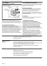
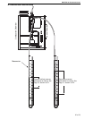
15.3.1 Electrode
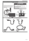
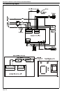
Figure 34: Burner Cup Position
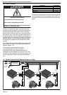
15.3.2 Burner Head/Injector Jet
When the cover is removed completely, the burner
assembly is exposed. Unscrew the burner cup. Remove
brass injector jet (orifice). Replace in reverse sequence.
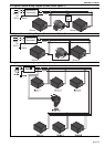
15.3.3 Solenoid Valve/Governor
Remove burner head. Unscrew two screws securing the
solenoid/governor body. Withdraw the electrical
connector and remove the flexible gas line connector. The
solenoid/governor and fittings can now be withdrawn from
the compartment. To ensure IP55 protection, replace the
gasket on the gas valve inlet flange (P/N 03200100).
The solenoid(s) can be removed from the body by
unscrewing central screw. Replace in reverse sequence.
15.3.4 Automatic Flame Control Unit
Remove black ignition lead. Withdraw the 10 point edge
connector. Unscrew two screws from the cover. Replace if
faulty. Refit in reverse sequence.
15.3.5 Pressure Switch
Disconnect the two silicone tubes. Remove electrical
plug. Remove one screw which secures the pressure
switch to the burner. Remove pressure switch.
Replace pressure switch, if faulty, and refit in reverse
sequence ensuring that the rubber tubes are reconnected
to the switch correctly.
15.3.6 Neons
Remove the two push on connectors and unscrew the
nut. Replace in reverse sequence.
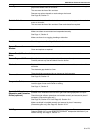
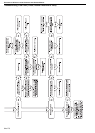
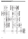
15.4 Maintenance Checklist
Installation Code and Annual Inspections:
All installation and service of ROBERTS GORDON
®
equipment must be performed by a contractor qualified in
the installation and service of equipment sold and
supplied by Roberts-Gordon LLC and conform to all
requirements set forth in the ROBERTS GORDON
®
manuals and all applicable governmental authorities
pertaining to the installation, service and operation of the
equipment.
To help facilitate optimum performance and safety,
Roberts-Gordon LLC recommends that a qualified
contractor conduct, at a minimum, annual inspections of
your ROBERTS GORDON
®
equipment and perform
service where necessary, using only replacement parts
sold and supplied by Roberts-Gordon LLC.
Burner Cup
(center horizontally)
Electrode
Assembly
16 mm
Air Plate
Jet
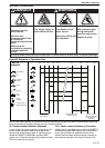
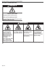
The Vicinity of the Heater
Do not store or use flammable objects, liquids or vapours near the heater.
Immediately remove these items if they are present.
See Page 5, Section 3.
Vehicles and Other
Objects
Maintain the clearances to combustibles.
Do not hang anything from, or place anything on, the heater.
Make sure nothing is lodged underneath the reflector, in between the tubes or in the
decorative or protective grilles (included with select models).
Immediately remove objects in violation of the clearances to combustibles.
See Page 5, Section 3.
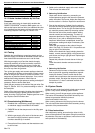
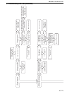
Reflector
Support reflector with reflector hanger and support strap.
Reflector must not touch tube.
Make sure there is no dirt, sagging, cracking or distortion.
Do not operate if there is sagging, cracking or distortion.
Make sure reflectors are correctly overlapped.
Clean outside surface with a damp cloth.